ADTRAN NetVanta 1560-08-150W Quick Start Manual Download Page 2

2

617108108PF2-13D

Installation Overview

To install the switch, you will need to do the following:

1. Mount the switch
2. Connect AC Power
3. Install SFP Modules

Installation Steps

To install the NetVanta 1560-08-150W switch, complete the following steps:

Mount The Switch

The switch can be mounted in a 19-inch rack, on a desk or shelf, or on a wall.

Mounting in a 19-inch Rack

g

     NOTE

Mounting brackets are not included. Mounting brackets may be ordered from ADTRAN using the following part number: 1700518F1

To mount the switch into a 19-inch rack, complete the following steps.

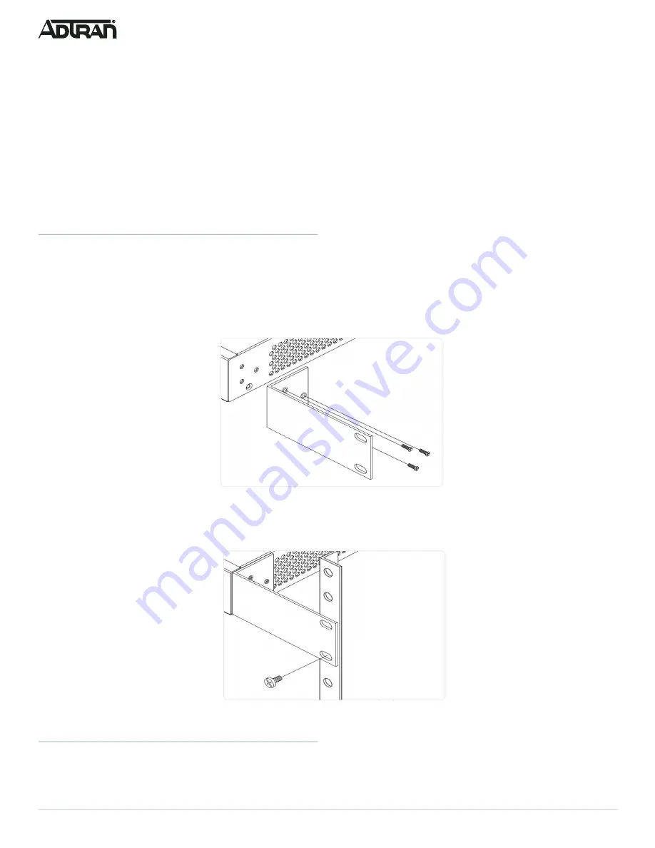
1. Attach the mounting brackets to both sides of the chassis. Insert the screws and tighten them with a screwdriver to secure the brackets.

Figure 3. Attaching Brackets to the Switch

2. Place the switch on a rack shelf in the rack. Push it in until the oval holes in the brackets align with the mounting holes in the rack posts. 
3. Secure the brackets to the posts by inserting rack screws and tightening them with an appropriate screwdriver.

Figure 4. Attaching Brackets to the Rack Post

Mounting on a Desk or Shelf

To mount the switch on a desk or shelf, complete the following steps.

1. Verify that the desk or shelf is sturdy enough to support the switch. 

Summary of Contents for NetVanta 1560-08-150W

Page 1: ...ur adhesive rubber feet Quick Start f WARNING The NetVanta 1560 08 150W is intended for indoor use only Ethernet PoE cables and attached equipment are intended for use within the same building with eq...

Page 2: ...the switch into a 19 inch rack complete the following steps 1 Attach the mounting brackets to both sides of the chassis Insert the screws and tighten them with a screwdriver to secure the brackets Fi...

Page 3: ...r sufficient air flow Mounting on a Wall To mount the switch on a wall complete the following steps 1 Using the mounting holes on the bottom of the unit as a template install the user supplied screws...

Page 4: ...intended for use with a Class 1 Laser module that complies with FDA 21 CFR 1040 10 1040 11 and IEC 60825 1 For continued compliance with the above standards only approved Class 1 Laser modules from an...

Page 5: ...ss 3 Power up the switch to be initially configured and wait until it has finished its start up processes 4 Connect the PC to any port on the switch using a standard Ethernet cable and check the port...

Page 6: ...in link act speed mode PoE Mode LED The PoE Mode LED indicates the port status LEDs are displaying in PoE mode Port Status LEDs The Port Status LEDs indicate the current status of each port in either...

Page 7: ...0 Mbps Off The port has no active network cable connected or has not established a link to connected device Otherwise the port may have been disabled through the switch user interface LED Color State...

Page 8: ...nt port in order to identify if it is related to the cable or specific port 4 Check if the port is disabled in the configuration settings via web user interface Port Status LED is OFF when the PoE LED...

Reviews: