


834-v6 Gigabit Router QSG
Understanding the Status LEDs
6SDG834V6-13A
3
Wall Mount Installation
The 834-v6 can be mounted on a wall. Wall Mount Kit (17600193F1) can be ordered for mounting the 834-v6. Instructions are provided in the
related Quick Start Guide (617600193F1-13).
Supplying Power to the device
1. Connect the small end of the power adapter to the
Power
port on the back panel of the SDG.
2. Plug other end of the power adapter into the wall outlet.
3. The SDG will begin powering up immediately as the 834-v6 has no on/off power switch.
4. Confirm that the power is connected properly. The
Multi-function Status
LED should be lit on the front of the gateway.
Subscriber Connections
The following subscriber connections are available on the back of the 834-v6:
■ 4x 1G Ethernet port (RJ45 Connector) –
LAN
port
■ 1x 1G Ethernet port (RJ45 Connector) -
WAN
port
■ 1x POTS port for voice
To connect the Ethernet interfaces, refer to
and insert a Category 5E (or better) RJ45 cable into the LAN port (labeled
LAN
) and the
WAN port (labeled
WAN
) until there is an audible “click”.
If a POTS device is required, use an RJ14 cable (not included) to connect the telephone device to the port labeled
Tel 1/2
on the rear of the
834-v6. Additional pinout details for this jack are available in the User Manual for the 800 series SDGs.
The
USB 3.0
host
port is reserved for future use. This port currently pr5 VDC for charging external USB devices.
Resetting the SDG
A reset button is available if the 834-v6 needs to be rebooted or restored to factory defaults. To reboot the 834-v6, press the
Reset
button on the
back panel of the device for less than
5 seconds
. To reset the device to factory defaults, press the
Reset
button for
5 seconds
or more
.
Activating WiFi Protected Setup™
WiFi Protected Setup™ (WPS) is a standard means for creating secure connections between the 834-v6 and various wireless client devices.
This feature is designed to simplify the pairing process between the devices. Perform the following steps to activate WPS:
1. Press the WPS button on the back of the 834-v6 for less than 5 seconds for 5GHz or more than 5 seconds for 2.4GHz.
2. The WPS LED on the back of the unit is steady green when WPS is on and flashing green when WPS is passing traffic.
3. WPS search mode continues for 2 minutes. The next step must be completed before the 2 minutes have lapsed.
4. In the WiFi settings for the LAN device to be connected to the local network, locate and select the name of the wireless network (SSID) to
which you want to connect. The 834-v6 should complete the connection without requiring the password to be manually entered.
Understanding the Status LEDs
A multifunction status LED on the front of the unit and status LED’s on the back panel allow you monitor the device status.
Multifunction Status LED
The multifunction status LED on the front of the unit indicates the device status.The meaning of the LED state is different depending on whether
the unit is running SmartOS or PlumeOS.
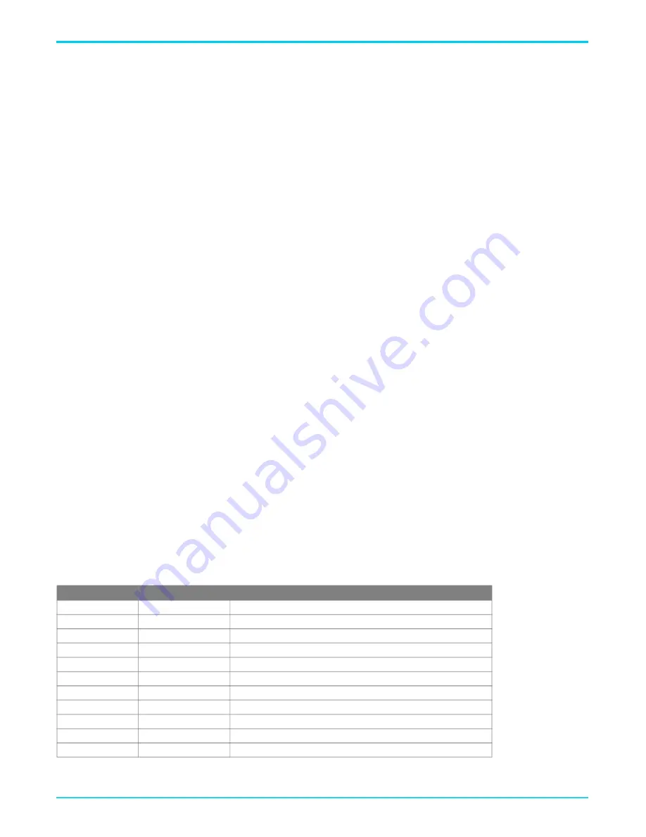
defines the multifunction status LED state when running SmartOS.
Table 2: Multifunction Status LED for SmartOS
Color
LEDState
Event
Blue
Solid
Cold boot
Red
Pulsing
Reboot and System Upgrade (persists over uboot)
Green
Pulsing
Linux booting up
Green
Blue Pulsing
Quick start
White
Solid
Hub WAN up, Internet
Red, Green, Amber
Pulsing
Hub WAN down, no Internet
Blue
Red Pulsing
Satellite Set Up
White
Solid
Satellite up
White
Red Pulsing
Satellite up, fair signal
Red, Green, Amber
Pulsing
Satellite up, poor signal
White
Pulsing
Reverting


