2
61287787F1-13A
4. Slide the Micro ONT over the Pan Head screws and exert a
small amount of downward pressure to ensure that the top of
the slots are resting on the shafts of the Pan Head screws.
Desktop Installation
The Micro ONT can be located on a desktop. Ensure the Micro
ONT is not located in direct sunlight, next to any thermal obstruc-
tions, or sources of moisture., water or other liquids.
Step 2: Connect Ethernet
The Micro ONT supports a Gbps (10/100/1000BASE-T)
connection to an RJ-45-type connector (
LAN
).
and Insert the CAT 6 rated cable in the RJ-45
LAN
Port.
Step 3: Connect POTS
Insert the RJ-11 connector in the RJ-11 jack labeled
VOICE
.
Step 4: Connect Fiber
f
WARNING!
CLASS 1 LASER PRODUCT
LASER RADIATION
1310 nm
Do not view directly with optical instruments.
This product contains a Class 1 Laser module that complies with
21 CFR 1040.10 and 1040.11 and IEC 60825-1.
Use of controls or adjustments or performance of procedures
other than those specified herein may result in hazardous
radiation exposure.
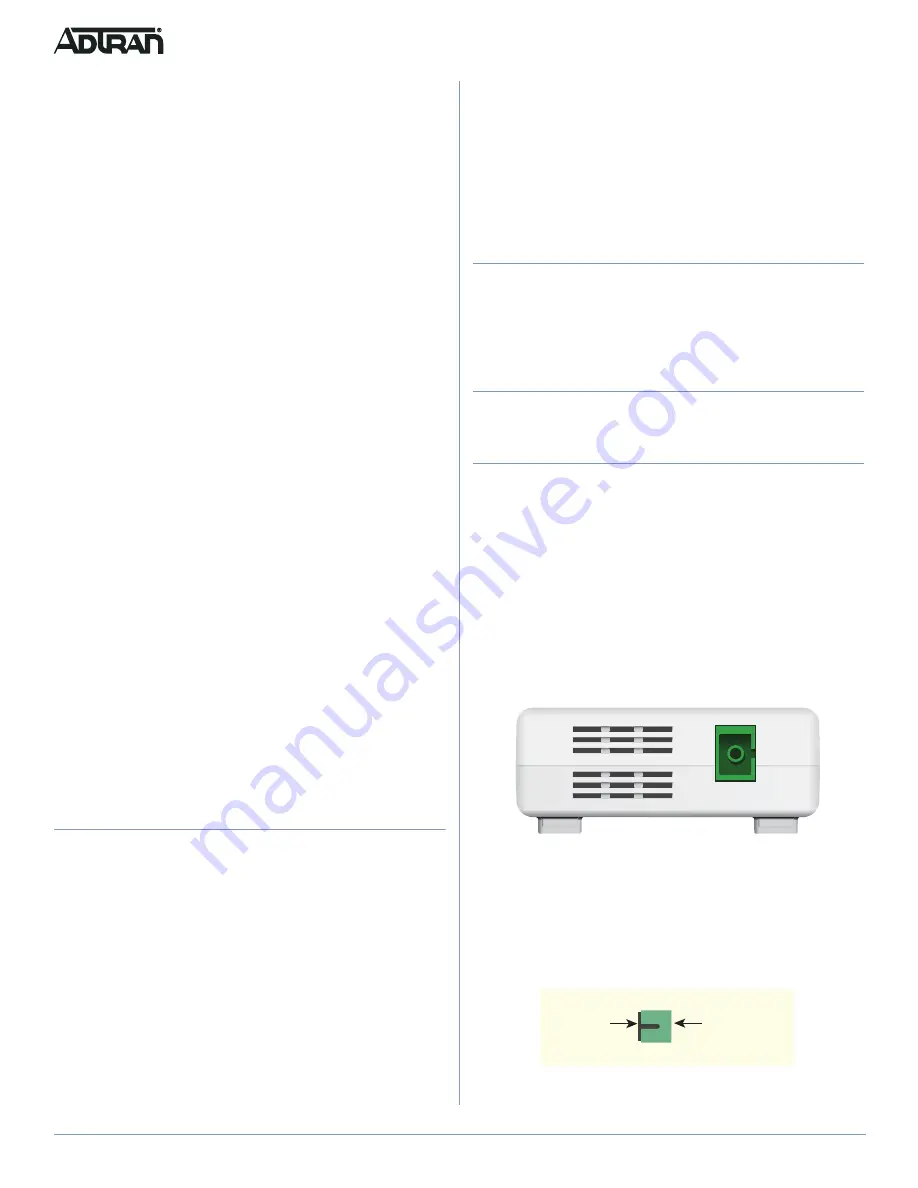
Figure 2. GPON Connection
Fiber is installed in an SC/APC connector (FIBER) located on the
rear of the Micro ONT (see
Complete the following steps to install fiber.
1. Refer to
and pull the Protective Cover from the SC/
APC Connector.
Figure 3. SC/APC Protective Cover
2. Clean the ends of the Incoming Fiber Connector.
CLASS 1 LASER
PRODUCT
Protective
Cover
SC/APC
Connector
I
NSTALLATION
Before installing the Micro ONT, inspect it for damage. If damage
has occurred during shipping, file a claim with the carrier and then
contact ADTRAN. For more information, refer to the warranty.
Installation Guidelines
The following are guidelines for this installation.
■
Read all warnings and cautions before installing or servicing
the Micro ONT.
■
Do not locate the Micro ONT in direct sunlight or next to any
thermal obstructions.
■
When the SC/APC fiber connection is not in use, replacing the
Protective Cover will help keep the optical connection clean.
■
This product should not come in contact with water or other
liquids.
Installation Overview
To install the Micro ONT, you will need to complete the following
steps:
■
Step 1: Position the Micro ONT
■
Step 2: Connect Ethernet
■
Step 3: Connect POTS
■
Step 4: Connect Fiber
■
Step 5: Connect 12 VDC Power or UPS Power
Required Tools
Standard technician tools and those listed below are required for
installing the Micro ONT.
■
PON power meter with wavelength filtering
■
Fiberscope or videoscope
For fiber optic connections, the following are required:
■
ODC Fiber cleaning tool
Installation Steps
To install the Micro ONT, complete the following steps.
Step 1: Position the Micro ONT
The Micro ONT can be mounted on a wall, or on a desktop.
Wall Mount Installation
To wall mount the Micro ONT complete the following steps:
g
NOTE
Refer to
when installing the Micro ONT on a wall.
1. Determine a location for the Micro ONT
2. Use the key holes (2 inches apart) on the back of the Micro
ONT as a template and install two #6 drywall anchors.
3. Install two #6 Pan Head screws. Leave approximately 1/4
inch protruding from the mounting surface.


