61287786F1-13A
3
Step 4: Connect 12 VDC Power
and the following steps when connecting power.
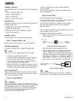
The Micro ONT is powered by a 12 VDC connection.
12 VDC Connection
To power the Micro ONT, complete the following steps:
1. Plug the supplied 12 V AC/DC power converter into the
PWR
connection.
2. Connect the power plug to a standard AC outlet. This
immediately turns the unit ON.
LED S
TATUS
The LEDs are located beneath the plastic housing and are only
visible after power has been applied. The following table provides
the LED status during normal operations.
Label
Status
Indication
LAN
2
Off
Green
Green Flashing
Fast
LAN Port is not connected
LAN Port is connected, but
data is not being transmitted
LAN Port is connected, and
data is being transmitted
FIBER
2
Off
Green
Green Flashing
Fast
ONT is not active (not Ranged)
ONT is active (Ranged)
ONT Is Activating (Ranging is
progress)
POWER
Off
Green
ONT power is Off
ONT power On
T
ROUBLESHOOTING
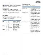
The following table provides troubleshooting tips.
Problem
Possible Solution
The FIBER LED contin-
ues flashing Green
■
Use an optical power meter to check
the receiving power to see if it between
–27 dbm and –8 dbm.
■
Reset the ONT using the Reset button.
If the ONT fails again, replace the ONT
with another unit.
The Power LED is Off
■
Make sure the power cable connector
is properly seated in the ONT power
input.
■
Verify that the power adapter is
plugged into a live AC outlet.
■
Check the power cable for shorts or
breaks.
■
Disconnect the power input connector
at the ONT; use a voltmeter to verify
that the proper voltage level is present
on the 12 V pin (power and power
return) from the power adapter.
The LAN LED is green
■
During boot-up, the LED will flash
green. This is normal. Once boot-up is
complete, the LED will illuminate solid
green. When data is transmitted, the
LED will flash green. If the LED
remains solid green, contact the
Central Office to verify that the ONT
serial number, password, and vendor
ID match those provisioned in the
database.
■
If provisioning is correct, have the
Central Office determine if there are
alarms on the PON feeding the ONT. If
no alarms exist, use an optical power
meter to troubleshoot the fiber
network.


