2
61287786F1-13A
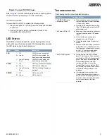
The Micro ONT supports a 1 Gbps (10/100/1000BASE-T)
connection (
LAN
).
and insert a Category 5e or better Ethernet
cable in the
LAN
Port.
Step 3: Connect Fiber
Do not view directly with optical instruments.
This product contains a Class 1 Laser module that complies with
21 CFR 1040.10 and 1040.11 and IEC 60825-1.
Use of controls or adjustments or performance of procedures
other than those specified herein may result in hazardous
radiation exposure.
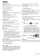
Fiber is installed in an SC/APC connector (FIBER) located on the
rear of the Micro ONT (see
Complete the following steps to install fiber.
1. Refer to
and remove the protective cover from the
SC/APC Connector.
Figure 2. SC/APC Protective Cover
2. Clean the ends of the incoming fiber patch cord.
3. Before installing the fiber, use an optical power meter to
measure the power level. The power level should not
exceed –8.0 dBm. Use an appropriate bi-directional optical
attenuator if the power levels are at or above –8.0 dBm. A
level between –8.0 dBm and –27.0 dBm is acceptable, but
levels between –12.0 dBm and –18.0 dBm are optimal.
4. Refer to
and connect the incoming fiber patch cord.
Figure 3. Fiber Installed
g
NOTE
When the SC/APC fiber connection is not in use, replace the
protective cover. This will help keep the optical connector clean.
SC/APC
Connector
Protective
Cover
3.625 x 3.625
Incoming Fiber
Patch Cord
Installation Overview
To install the Micro ONT, you will need to complete the following
steps:
■
Step 1: Position the Micro ONT
■
Step 2: Connect Ethernet
■
Step 3: Connect Fiber
■
Step 4: Connect 12 VDC Power
Required Tools
Standard technician tools and those listed below are required for
installing the Micro ONT.
■
Optical power meter with wavelength filtering
■
Fiberscope or videoscope
For fiber optic connections, the following is required:
■
ODC Fiber cleaning tool
Installation Steps
To install the Micro ONT, complete the following steps.
Step 1: Position the Micro ONT
The Micro ONT can be mounted on a wall, or on a desk top.
Wall Mount Installation
To wall mount the Micro ONT complete the following steps:
g
NOTE
Refer to
when installing the Micro ONT on a wall.
1. Determine a location for the Micro ONT.
2. Use the key holes (2 inches apart) on the back of the Micro
ONT as a template and install two #6 drywall anchors.
3. Install two #6 pan head screws. Leave approximately 1/4
inch protruding from the mounting surface.
4. Slide the Micro ONT over the pan head screws and exert a
small amount of downward pressure to ensure that the top of
the slots are resting on the shafts of the pan head screws.
Desk Top Installation
The Micro ONT can be located on a desk top. Ensure the Micro
ONT is not located in direct sunlight, next to any thermal obstruc-
tions, sources of moisture, or liquids.
Step 2: Connect Ethernet
f
CAUTION!
The product is intended for indoor use only. Ethernet cable and
attached equipment are intended for use within the same building
with equipotential bonding, and not intended to be placed in
separate buildings or structures. Failure to deploy as described
could result in permanent damage from lightning or other
electrical events and voids the warranty.


