


NetVanta 1230 Series Hardware Installation Guide
Physical Descriptions
61702594G1-34C
Copyright © 2013 ADTRAN, Inc.
17
LED Mode Switch (Future Release)
The LED mode switch is located on the left side of the unit and is used to toggle Ports
1
through
24
between link/activity and VCID display modes.
Link/Activity LEDs
The link/activity LEDs labeled
1
through
24
are located above the 10/100Base-T Ethernet interfaces
and indicates when there is activity on the interface. When the LED mode switch has been activated,
these LEDs will display VCID (future release).
10/100Base-T Ethernet Interfaces
The front panel contains 24 10/100Base-T Ethernet interfaces (RJ-45). These interfaces are arranged in
stacked pairs, with the numbers
1
through
24
screened directly above corresponding ports.
100/1000Base-T Gigabit Ethernet Interfaces
The front panel contains two 100/1000Base-T Gigabit Ethernet interfaces (RJ-45) labeled
G1
and
G2
.
Status LEDs
G1
and
G2
are shared with SFP slots
G1
and
G2
and are located on the upper right corner
of the unit.
SFP Slots
The front panel contains four standard SFP slots for fiber connectivity numbered
G1
through
G4
with
Status LEDs located on the upper right corner of the unit. SFP slots
G1
and
G2
are associated with the
Gigabit Ethernet (RJ-45) interfaces numbered
G1
and
G2
and share status LEDs. (Use either the RJ-45
connectors for up 100/1000 Mbps copper connectivity or the SFP slots for 1 Gbps fiber connectivity.
The SFP slots have precedence.) Slots
G3
and
G4
provide fiber connectivity at 1 or 2.5 Gbps.
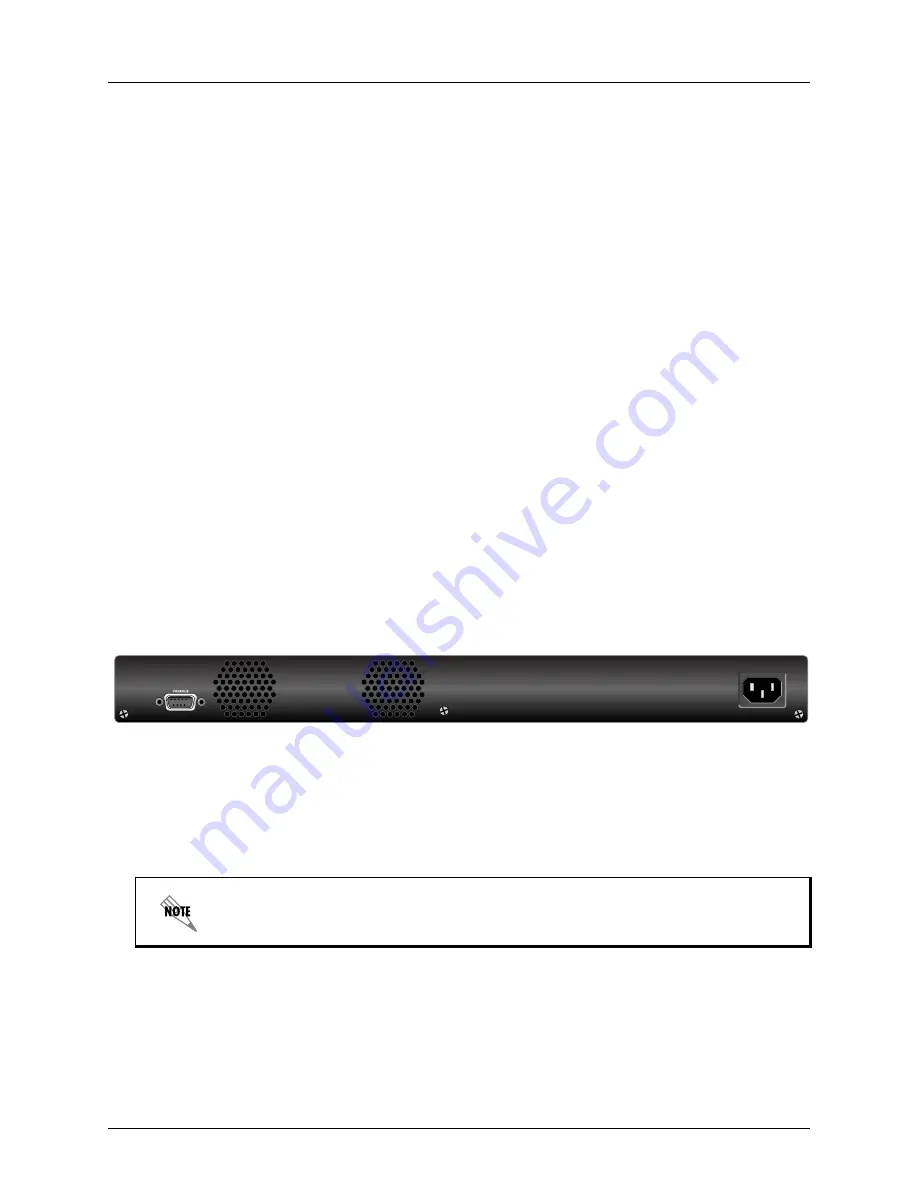
NetVanta 1234P Rear Panel Design
The NetVanta 1234 rear panel is shown below.
Figure 4. NetVanta 1234P Rear Panel Layout
NetVanta 1234P Rear Panel Interfaces
CONSOLE Interface
The
CONSOLE
interface is an EIA-232 serial port (DCE) that provides for local management and
configuration (via a DB-9 female connector).
Power Connection
The rear panel has a power input to the AC universal power supply. Please refer to
Supplying Power to
the Unit on page 26
for connection details.
Connection directly to an external modem requires a cross-over cable.
AC INPUT


