


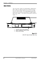


Chapter 2. Installation
10
Dual DSU-DP User Manual
6120 0 .128 L1 -1
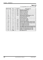
Table 2-B
Pin Assignments for Primary V.35 Cable
Description
ing Indicator (RI)
ocal Loopback (LL)
HD Pin #
Pin
CCITT
1
A
101
Protective G round (PG )
7
B
102
Signal Ground (SG)
4
C
105
Request to Send (RS)
5
D
106
Clear to Send (CS)
6
E
107
Data Set Ready (SR)
8
F
109
Received Line Signal Detector (CD)
2 0
H
-
Data Terminal Ready (TR)
1 7
J
-
R
1 8
L
-
L
1 1
R
104
Received Data (RD-A)
1 2
T
104
Received Data (RD-B)
2 4
V
115
Receiver Signal Element Timing (SCR-A)
2 5
X
115
Receiver Signal Element Timing (SCR-B)
9
P
103
Transmitted Data (SD-A)
1 0
S
103
Transmitted Data (SD-B)
2 2
Y
114
Transmitter Signal Element Timing (SCT-A)
2 3
AA
114
Transmitter Signal Element Timing (SCT-B)
1 3
U
113
External TX Signal Element (SCX-A)
2 6
W
113
External TX Signal Element (SCX-B)
1 9
K, NN
-
Test Indicator (TI)


