OPC7000 series
34
© ads-tec Industrial IT GmbH • Heinrich-Hertz-Str. 1 • 72622 Nürtingen • Germany
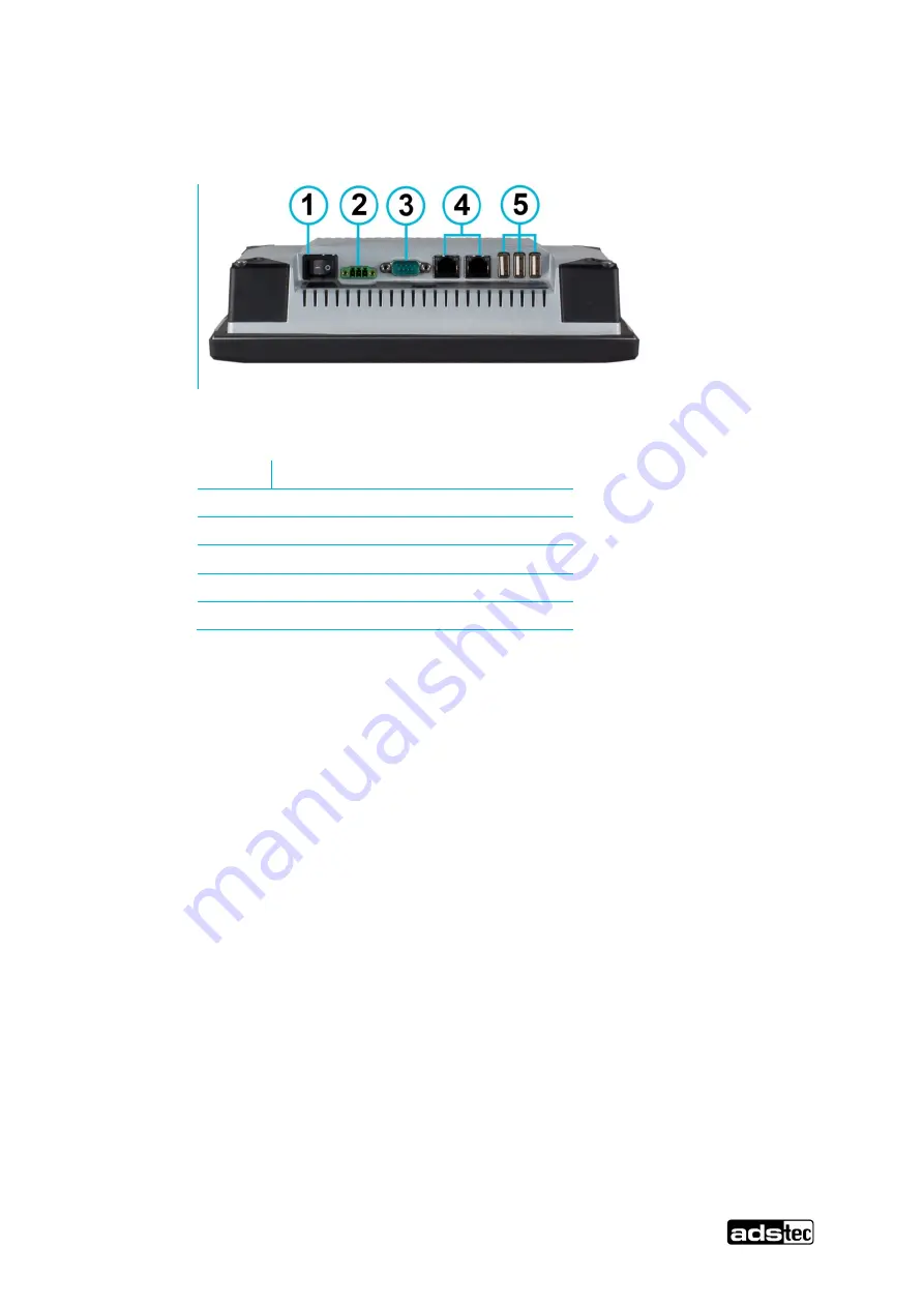
5.1 Available Interfaces (OPC7008)
Abb. 8: Variante 1
Nr.
Description
1
On-/Off Switch
2
Power Supply 24 V DC
3
1 x COM-Port
4
2 x LAN
5
3 x USB 2.0
Page 1: ...Updated 2019 04 04 Instruction manual Industrial PCs OPC7000 series Version 2 4 Translation of the original instruction manual...
Page 2: ...perating and safety instructions 13 3 1 Operating location 14 3 2 Damage due to improper use 14 3 3 Warranty repairs 14 3 4 Intended use 15 3 5 Improper use 15 3 6 Treatment and disposal of lithium ba...
Page 3: ...24V DC 41 7 2 USB connections 41 7 3 Network connection RJ45 42 7 4 Serial interface COM RS232 43 8 Drives 44 8 1 Hard disk Flash SSD 44 8 2 External drives 44 9 Software 45 9 1 Configuration Center 4...
Page 4: ...ginal version of this instruction manual was written in German All non German versions of this instruction manual are translations of the German instruction manual 1 2 Limitation of liability ads tec...
Page 5: ...ormation for installation commissioning and operation of the device along with technical data of the device hardware Website You can download drivers software user manuals leaflets and flyers about th...
Page 6: ...assifies the hazard Instructions for preventing the hazard are identified by an arrow 2 3 Explanation of used symbols DANGER Indicates an imminent danger If not avoided death or severe injury will res...
Page 7: ...OPC7000 series 6 ads tec Industrial IT GmbH Heinrich Hertz Str 1 72622 N rtingen Germany Tips and suggestions for the efficient use of the device and software optimisation are also provided...
Page 8: ...prepared to the best of our knowledge They do not represent any assurance for the properties themselves Despite taking utmost care no liability can be assumed for accuracy completeness and actuality...
Page 9: ...C only with Flash SSD for storage 30 to 75 C Temperature for OPC7013 7015 devices in operation 5 to 45 C in operation 20 to 60 C only with Flash SSD automotive hard disk or 2 5 Industrial SSD for sto...
Page 10: ...U conformity declaration can be requested at http www ads tec de support support anfrage html and is available for download at http www ads tec de support download eg konformitaetserklaerung html Reco...
Page 11: ...y and precision in a new form Optimised in every detail with multi touch operation and rear service access for simple and safe replacement of all components In wide screen format in four different siz...
Page 12: ...OPC7000 series 11 ads tec Industrial IT GmbH Heinrich Hertz Str 1 72622 N rtingen Germany Rear side Fig 2 No Description 4 Service slot 5 Tensioners for installation purposes...
Page 13: ...OPC7000 series 12 ads tec Industrial IT GmbH Heinrich Hertz Str 1 72622 N rtingen Germany Rear side Fig 3 No Description 4 Tensioners for installation purposes 5 Service slot...
Page 14: ...formation All users must read this manual and have access to it at all times Installation commissioning and operation may only be performed by qualified and trained personnel The safety notices and th...
Page 15: ...erature fluctuations The device should only be switched on after it has acclimated to the ambient temperature To avoid overheating in operation The device must not be exposed to direct radiation by su...
Page 16: ...or applications for which further approvals beyond the manufacturer s declaration are necessary e g applications with explosion hazard medical technology shipping industry The device must not be put i...
Page 17: ...ld not be exposed to fire soldered recharged opened short circuited reversed or heated above 100 C and they should be disposed of properly as well as protected against sunlight humidity and condensati...
Page 18: ...ice can be caused by electrostatically sensitive components All installation and service work performed on the device must be performed only under safe secure and de energised conditions Recommendatio...
Page 19: ...The device must not be exposed to direct radiation by sunlight or any other light source If the device is installed in a panel casing or similar it must be ensured that no heat accumulation occurs Th...
Page 20: ...OPC7000 series 19 ads tec Industrial IT GmbH Heinrich Hertz Str 1 72622 N rtingen Germany 4 2 External device dimensions OPC7008 Abb 4...
Page 21: ...OPC7000 series 20 ads tec Industrial IT GmbH Heinrich Hertz Str 1 72622 N rtingen Germany 4 3 External device dimensions OPC7008...
Page 22: ...OPC7000 series 21 ads tec Industrial IT GmbH Heinrich Hertz Str 1 72622 N rtingen Germany 4 4 External device dimensions OPC7013 Fig 5...
Page 23: ...OPC7000 series 22 ads tec Industrial IT GmbH Heinrich Hertz Str 1 72622 N rtingen Germany 4 5 Installation layout OPC7013...
Page 24: ...OPC7000 series 23 ads tec Industrial IT GmbH Heinrich Hertz Str 1 72622 N rtingen Germany 4 6 External device dimensions OPC7015 Fig 6...
Page 25: ...OPC7000 series 24 ads tec Industrial IT GmbH Heinrich Hertz Str 1 72622 N rtingen Germany 4 7 Installation layout OPC7015...
Page 26: ...OPC7000 series 25 ads tec Industrial IT GmbH Heinrich Hertz Str 1 72622 N rtingen Germany 4 8 External device dimensions OPC7022 Fig 7...
Page 27: ...OPC7000 series 26 ads tec Industrial IT GmbH Heinrich Hertz Str 1 72622 N rtingen Germany 4 9 Installation layout OPC7022...
Page 28: ...installation ATTENTION The grub screw of the Quick Snap element must not protrude when folding in but must rather be flush with the tensioner Non compliance may result in damage to the device ATTENTI...
Page 29: ...er of installation OPC7008 ACHTUNG The screws have to be tighten with a torque of 0 25 NM 1 Before the device can be integrated in the panel the tensioner fixing screws must be loosened until the tens...
Page 30: ...ch Hertz Str 1 72622 N rtingen Germany 2 Now position the device inside the installation recess ATTENTION In order to position the device correctly the opened tensioners should be held back by hand wh...
Page 31: ...OPC7000 series 30 ads tec Industrial IT GmbH Heinrich Hertz Str 1 72622 N rtingen Germany 3 Fasten the tensioner screws with 0 25 NM until once the device is installed in the recess Item...
Page 32: ...nection No earthing connection needs to be established as earthing takes place via the protective earth of the device plug power supply connection In the event of additional earthing on the earthing s...
Page 33: ...bH Heinrich Hertz Str 1 72622 N rtingen Germany 3 The device must be carefully pushed into the cabinet Then the tensioners snap forward again The device is now secured in the installation recess 4 The...
Page 34: ...ff before connecting or disconnecting any cables in order to prevent damage to the electronics The device may only be switched on after acclimatising to the ambient temperature in order to avoid conde...
Page 35: ...4 ads tec Industrial IT GmbH Heinrich Hertz Str 1 72622 N rtingen Germany 5 1 Available Interfaces OPC7008 Abb 8 Variante 1 Nr Description 1 On Off Switch 2 Power Supply 24 V DC 3 1 x COM Port 4 2 x L...
Page 36: ...Germany 5 2 Available interfaces OPC7013 7022 Abb 9 Variante 1 Nr Description 1 On Off Switch 2 Power Supply 24 V DC 3 1 x COM Port 4 5 x USB 2 0 5 3 x LAN Abb 10 Variante 2 Nr Description 1 On Off S...
Page 37: ...es into terminals Connect cable for serial parallel data transmission and fasten the plugs to the sockets Plug in all other required cables and secure against slipping out Pos 19 D atentechni k Inbetr...
Page 38: ...evel 2 Decrease display brightness Level 1 Change task Alt ESC in Windows Level 2 Increase display brightness Level 1 F2 on keyboard Level 2 Level 1 Right mouse key function Level 2 Shift key SHIFT fo...
Page 39: ...on a real keyboard Inside Bios Setup the key reacts like the Down Key on a real keyboard SHIFT Key for selecting second keyboard layer The Key has to be pressed simultaneously with the required functi...
Page 40: ...entations Alphanumeric keys Numeric keys Function key bar Soft keyboard representation zoom in Soft keyboard representation zoom out Information If functions are to be called for which two keys must b...
Page 41: ...is already integrated in the respective operating system Pos 23 D atentechni k Bedienung Status Anzeig en SYS LED SYS LED f r VMT60xx Serie 2 mod_1260525540269_6 doc 6876 Note The corresponding drive...
Page 42: ...A 10ms T 60xx 1 mod_1246631044840_6 doc 5885 Pos 29 D atentechni k Schnittstell en USB Anschluss U SB Anschl uss f r VMT 60xx 2 mod_1260457598122_6 doc 6860 7 2 USB connections The USB interfaces are...
Page 43: ...network topology must be observed If the drivers required for function are not installed they can be installed from the website www ads tec de 10 100Mbit Pin Number Signal Name 1 TX 2 TX 3 RX 4 NC 5 N...
Page 44: ...interface COM RS232 The serial interface is used for digital data transmission The RS232 interface can be connected by using a commercially available 9 pin SUB D cable PIN number Signal name 1 DCD 2...
Page 45: ...er ne Laufwerke Exter ne Laufwer ke f r OPC 5112 5115 5117 IPC 1100 CPC PLC OTC ITC VMT Serie 0 mod_1158926656205_6 doc 563 8 2 External drives External storage media can be connected via USB interfac...
Page 46: ...red for installation Installing the operating system The device does not have any integrated CD drive The installation of the operating system can therefore only be carried out by using the USB interf...
Page 47: ...GHz RAM 4 GB DDR3 4 GB DDR3 8 GB DDR3 Graphics controller A minimum of 8 MB shared memory Intel HD Graphics at Celeron 847E DirectX 10 1 and OpenGL 3 1 Support Intel HD Graphics 3000 bei i5 2515E i7...
Page 48: ...261 x 64 mm 413 x 290 x 68 mm 553 x 355 x 68 mm Installation depth 50 mm 51 mm 54 mm 54 mm Installation recess 240 x 176 mm 332 x 240 mm 392 x 269 mm 532 x 334 mm Weight Approx 1 9 kg Approx 2 8 kg A...
Page 49: ...tware installations please contact the system supplier in question as ADS TEC will not be able to answer such questions ADS TEC does not provide support services for any device that was not purchased...
Page 50: ...72622 N rtingen Germany 12 Component replacement ATTENTION Make certain that all cables are disconnected and that no voltage is connected to the device 12 1 Opening the service slot OPC7008 Remove the...
Page 51: ...ries 50 ads tec Industrial IT GmbH Heinrich Hertz Str 1 72622 N rtingen Germany Fig 14 By removing the service slot cover it is possible to replace the following components 1 Lithium battery 2 mSATA c...
Page 52: ...rmany 12 2 Opening the service slot OPC7013 7022 Remove the four screws for the service slot on the rear of the device The screws can be removed with a size Tx 10 screwdriver The rear cover can be til...
Page 53: ...ds tec Industrial IT GmbH Heinrich Hertz Str 1 72622 N rtingen Germany Fig 16 By removing the service slot cover it is possible to replace the following components 1 HDD 2 Fan 3 RAM 4 Lithium battery...
Page 54: ...g the external tabs with a flat tool screwdriver Installing replacing the battery The lithium battery can now be removed It may only be replaced with a battery of the same type The type of battery to...
Page 55: ...622 N rtingen Germany 12 4 Replacing the HDD hard disk OPC7013 7022 Removal The extraction aid provided on the HDD should be used for removing the HDD Carefully pull out the HDD Installation The HDD m...
Page 56: ...fan OPC7013 7022 ATTENTION Before the device fan can be replaced the fan cable must be unplugged Removal Use a size Tx 10 screwdriver to remove the fan screws The fan can then be lifted out and repla...
Page 57: ...cing the working memory RAM OPC7013 7022 Removal The RAM memory is released by carefully pulling apart the retaining clips 1 2 It can now be replaced with new RAM memory Installation Insert the new RA...
Page 58: ...ermany 12 7 Replacing the mSATA modules OPC7000 series Information For the devices OPC7013 7022 the HDD hard disk must be removed before the SSD Flash Modules can be installed or replaced Remove the H...
Page 59: ...OPC7000 series 58 ads tec Industrial IT GmbH Heinrich Hertz Str 1 72622 N rtingen Germany Mounting OPC7000 Serie 1 Mainboard 2 plastic disc 3 plastic distance holder 4 mSATA Card 5 plastic disc...