background image

16

LED DISPLAY AND FUNCTION KEYS
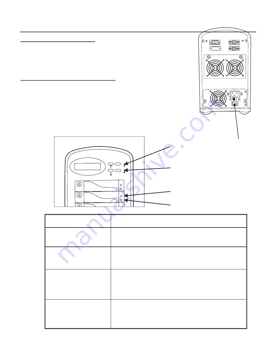
LED Display 

Shown below is the LED Display. Please refer to the illustration, 

the LEDs inform you of the Disk Array’s current operating 

status. Upon activating a certain function, the corresponding 

LED  indicator should turn on indicating that the feature is 

engaged.


 LED      


 Descriptions


1. Power ON  Indicator 


light up :


"Green"


, it lights when the Power Supply


is plugged and operating functionally.


2. Host Computer Access 


light up :


"Yellow"


, Indicates Host


Indicator


computer is currently accessing the Disk Array


 3. HDD Power-On Indicator


light up :


"Green"


, It lights when the HDD frame


is locked and Power-On

      HDD Error Indicator


light up :


"Red"

 , when the HDD not installed or error.


4. HDD Access Indicator


light up :


"Yellow"


, when HDD is access.   

1

2

3

4

ESC

Enter

Chapter 2 Getting Started


(

。・

) Up Arrow / Right Arrow            Use to scroll the cursor Upward / Rightward

   (

。・

) Down Arrow / Left Arrow         Use to scroll the cursor Downward / Leftward

   ( Enter )                                                       Use to confirm a selected item

   ( ESC )                                                           Use to exit a selection

POWER ON AND SELF TEST

When you connect the Disk Array to the Host computer, You 

should press the ON/OFF Switch ( O / I ) on the power supply, 

it will turn the Disk Array system on and the Self-Test will be  

started automatically.

Host Port

Terminal Port

Power Supply's On / Off Switch


 LED      


 Descriptions


1. Power ON  Indicator 


light up :


"Green"


, it lights when the Power Supply


is plugged and operating functionally.


2. Host Computer Access 


light up :


"Yellow"


, Indicates Host


Indicator


computer is currently accessing the Disk Array


 3. HDD Power-On Indicator


light up :


"Green"


, It lights when the HDD frame


is locked and Power-On

      HDD Error Indicator


light up :


"Red"

 , when the HDD not installed or error.


4. HDD Access Indicator


light up :


"Yellow"


, when HDD is access.   

1

2

3

4

ESC

Enter

Summary of Contents for API-960

Page 1: ...com Technical Support 562 926 4338 Technical Support Hours Technical Support Technical Support Hours Technical Support 8am 5pm M F PST Technical Support 8am 5pm M F PST Technical Support PYRO DV RaidR...

Page 2: ...0 6 RAID Level 1 7 RAID Level 3 8 RAID Level 5 9 Summary Comparison of RAID Levels 10 Supported RAID Levels 11 Chapter 2 Getting Started General Overview 12 Unpacking Checklist 12 Choosing a place fo...

Page 3: ...the supply voltage 9 The appliance must be grounded This product is equipped with a 3 wire grounding type power cord this power cord will only fit into a grounding type power outlet 10 If an extension...

Page 4: ...xtreme heat or cold Warning The Disk Array s LCD Panel may be damaged by exposure to intense sunlight Limit exposure to indirect or subdued sunlight only Your Disk Array should be used in a clean envi...

Page 5: ...des the processing and access power for you to handle complex and large files Selective RAID levels 0 1 0 1 3 or 5 Built in 64MB cache memory expandable up to 512MB Serial communication port Terminal...

Page 6: ...drives typically two to six which appear to the user to be equivalent to a single large capacity disk drive The remarkable benefit of disk array is that if any single disk in the RAID fails the syste...

Page 7: ...libraries for rapid loading these libraries are normally read only Storing large tables or other structures of read only data for rapid application access Like program images the data should be backed...

Page 8: ...nagement software simply directs all application requests to the surviving member RAID level 1 is suitable for data for which reliability requirements are extremely high or for data to which high perf...

Page 9: ...e of these types They operate on large data objects such as graphical image processing CAD CAM files and others They are non interactive applications that process large data sequentially They usually...

Page 10: ...hanced availability is worth protecting but for which the value of full disk mirroring is questionable High read request rates Small percentage of writes in I O load RAID level 5 arrays have unique pe...

Page 11: ...h provided 1 Mirroring All data Duplicated 1 disk Very High High 3 Parallel Data sector is subdivided N 1 Very Highest Transfer and distributed across all disks High of all Disks with data disk Redund...

Page 12: ...ction Disk Mirroring Disk drives are mirrored 1 All data is 100 duplicated on each 2 4 equivalent disk drives High Data Reliability Parallel Transfer Disks with Parity 3 Data is striped across physica...

Page 13: ...for doing regular backup It s highly recommended to conduct a backup strategy for critical data Unpacking Checklist Before unpacking your Disk Array prepare a clean and stable place to put the content...

Page 14: ...trolled by wall switches or automatic timers Accidental disruption of the power source may wipe out data in the memory of your computer or Disk Array Keep the entire system away from potential sources...

Page 15: ...n either on AC 115V 10 or AC 230V 10 Slide the AC voltage select switch on the power supply to the correct position which corresponds with the wall outlet supply voltage Warning Wrong AC Voltage input...

Page 16: ...2 Gently Pull out the HDD tray SCREWS SCREWS Cabling Step 3 Insert HDD into the tray Step 4 Screw in the hard drive Use the correct size type and thread Step 5 Cabling Connect the Data cable and Powe...

Page 17: ...ot installed or error 4 HDD Access Indicator light up Yellow when HDD is access 1 2 3 4 ESC Enter Chapter 2 Getting Started POWER ON AND SELF TEST When you connect the Disk Array to the Host computer...

Page 18: ...ol or icon corresponding to that function will appear in the display window The symbol will remain in the display window indicating the status of the Disk Array Identifying the status on the LCD The f...

Page 19: ...e to connect your Host computer to the Disk Array s built in IEEE 1394 adapter port Connect the Host computer as shown below Figure Host Linkage Chapter 2 Getting Started Caution For safety reasons ma...

Page 20: ...changes to the configuration and tailor your Disk Array to your individual needs The setup program is a ROM based configuration utility which displays the Disk Array s Status and allows you to set up...

Page 21: ...rformed through this interface Function Key Definitions The four function keys at the top of the front panel perform the following functions Up Arrow Right Arrow Use the scroll the cursor Upward Right...

Page 22: ...on 6 Set Hot Spare Disk Select Yes to set one Disk Drive as a Hot spare Disk Valid for RAID Level 5 and 3 the total number of Disk Drives installed must be more than 3 Disk Drives 7 Set Password Press...

Page 23: ...configure the VT100 terminal settings to the values shown below VT100 Termnal or compatible Set up Connection Serial Port COM1 or COM2 Protocol RS232 Asynchronous Cabling Null Modem cable Baud Rate 11...

Page 24: ...23 CONFIGURATION PROCEDURES VT100 Terminal CONFIGURATION PROCEDURES VT100 Terminal Chapter 3 CONFIGURATION MAIN SCREEN...

Page 25: ...D Select No for setting Password Select Yes for setting all the configurations SET RAID LEVEL Move the cursor to the desired RAID Level 0 1 3 5 0 1 None and Press Enter to confirm it Warning All Data...

Page 26: ...id in RAID level 5 and RAID level 3 the total Disk Drives installed must be more than 3 Disk Drives Disk Drives number 3 Chapter 3 CONFIGURATION SET PASSWORD Press Enter to activate the password setti...

Page 27: ...be lost if you change the RAID level Warning Saving configuration changes causes the disk array controller s working parameters to change This can produce unpredictable results if it occurs during Hos...

Page 28: ...Disk Array comes with 64MB of memory that is expandable to a maximum of 512MB These expansion memory module can be purchased from your dealer Memory Type 3 3V PC100 133 SDRAM 144pin DIMM Memory Size...

Page 29: ...Install the memory a The DIMM memory modules will only fit in one orientation b Press the memory module firmly into socket from a 45 degree angle make sure that all the contacts are aligned with the...

Page 30: ...NCED INFORMATION Host channel NVRAM LCD Terminal Port PCI BUS i960RM Local BUS PCI Bridge Main memory i960RM RISC Micro processor Flash EPROM Dual Channel IDE Controller Disk 1 Disk 2 Dual Channel IDE...

Page 31: ...2 Step 3 Enter a name for your Terminal Please configure the VT100 terminal setting to the values shown below VT100 terminal or compatible set up Connection Serial Port COM1 or COM2 Protocol RS232 As...

Page 32: ...31 Chapter 4 ADVANCED INFORMATION UPDATING FIRMWARE CONT D UPDATING FIRMWARE CONT D Step 4 Select a connecting port in your Terminal Step 5 Port parameter settings Step 6...

Page 33: ...Step 7 Select emulate VT100 model After you have finished the VT100 Terminal setup you may restart your Disk Array and press Ctrl D keys in your Terminal to linkthe Disk Array and Terminal together P...

Page 34: ...ess Y to download the new firmware and press Y again to confirm the Update WARNING Unpredictable results will occur if firmware update is attempted during Host computer and Disk Array activity All act...

Page 35: ...PC Step 5 Press Go to confirm to download the new firmware Step 6 Type Go to reconfirm and the firmware will begin to be reprogrammed Step 7 After verifying please restart the Disk Array to activate t...

Page 36: ...e the disk array is on The Hot Swap parts include Hard Disk Drives Cooling Fans Follow the steps below and refer to the diagrams to remove and install the Hot Swap parts REMOVING INSTALLING HARD DISK...

Page 37: ...isk Array s built in buzzer will sound and the intelligent Auto Rebuild function will not be started For best performance we recommend you swap with an identical Hard Disk Drive Step 5 Gently Slide in...

Page 38: ...e Step 2 Unplug the Fan connector Step 3 Unscrew the faulty cooling fan and replace with a good one Important The cooling fan s air flow must point to the fan door please refer to the label on the coo...

Page 39: ...EEPROM 256K x 8 Hardware XOR Accelerate Build In IEEE 1394 I O Processor TI TSB43AB22 Serial Port 1x RS232 Asynchronous Port Ba ud Rate 115 200 Bits Per Second Da ta Bits 8 Sto p Bit 1 Pari ty None R...

Page 40: ...Fans Power Supply Capacity 200W AC Input Voltage 115 230V 10 60 50 Hz Environmental Relative Humidity 10 to 85 Non condensing Temperature Operating 5 J 40 J Storage 25 J 60 J Safety testing Under appl...

Page 41: ...pped products 4 Replacement product cannot be shipped to you until the defective product has been received by ADS 5 Once the product is received at the factory it will be tested and then repaired or r...

Page 42: ...erican Office 12627 Hidden Creek Way Cerritos CA 90703 Phone 562 926 1928 Technical Support 562 926 4338 Technical Support Hours M F 8am 5pm PST Fax 562 926 0518 European Office Shannon Industrial Est...

Reviews: