


Advanced RF Technologies, Inc.
76
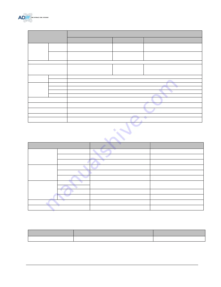
-SDR-AF
Parameters
Specifications
AF
Frequency
Range
DL
2110~2180 MHz
UL
1710~1755 MHz
Frequency Error
≤ ±0.05ppm
Band Selection
1.25MHz Step
Max 18.75 MHz
(Non-Contiguous 3ch)
Gain Flatness
Full band
≤ ±1.5dB
Each band
≤ ±1.5dB
Gain
Maximum
95dB
Step
0.5dB
Range
40dB
Tolerance
≤ ±1.0dB
Composite Output power
33dBm (SDR-33)
Delay
6us
Roll offs
1MHz@ 50dBc
Noise Figure( Uplink Only)
6dB@ Max Gain
VSWR (Input Only)
1.5:1
8.2
Mechanical Specifications
Table 8-2
Mechanical Specifications
Parameters
Specifications
Remarks
Size
Module
18.2 x 11.6 x 4.2 in
NMS
17 x 16.7 x 2.3 in
Chassis
19 x 19.1 x 14 in
Weight
Module
23 lbs
NMS
7 lbs
Chassis
26 lbs
Connector
Type
Input / Output
N Female
Sum Port
Ethernet
RJ45 Female
Frame ground
M5 Screw
Mount type
Wall mount or 19” rack mount
Security
Physical Cabinet
8.3
Power Specifications
Table 8-3
Power Specifications
Parameters
Specifications
Remarks
AC Power
110~130V AC / 210~240V AC
AC Select


