


viii
List of Figures
Figure 4-18: Example 1 - Arc Trajectory ...................................... 64
Figure 4-19: Velocity vs. Time...................................................... 64
Figure 4-20: Example 2 - Arc Trajectory ...................................... 65
Figure 4-21: Velocity vs. Time...................................................... 65
Figure 4-22: Adding Dwell Example............................................. 66
Figure 4-23: Velocity vs. Time...................................................... 66
Figure 4-24: Line & Line............................................................... 67
Figure 4-25: Line & Arc ................................................................ 67
Figure 4-26: Arc & Arc.................................................................. 67
Figure 4-27: Smoothing Example................................................. 68
Figure 4-28: Velocity vs. Time...................................................... 68
Figure 4-29: Move Ratio Control .................................................. 71
Figure 4-30: Pulse Input (Encoder Counter) Circuit ..................... 77
Figure 4-31: Line Driver Circuit .................................................... 78
Figure 4-32: Open Collector Circuit.............................................. 79
Figure 4-33: A/B Phase Timing .................................................... 80
Figure 4-34: OUT/DIR Pulses ...................................................... 80
Figure 4-35: DA Output ................................................................ 81
Figure 4-36: Notch Filter .............................................................. 99
Figure 4-37: Interrupt Control..................................................... 103
Figure 4-38: DSP Action Graph ................................................. 107
Figure 4-39: Interlock Area......................................................... 107
Figure 4-40: Trigger Output........................................................ 110
Figure 4-41: Triggering Frequency Under 500Hz ...................... 111
Figure 4-42: Positive Move ........................................................ 113
Figure 4-43: Negative Move....................................................... 114
Figure 4-44: Conceptual Flow Chart - Timing A......................... 116
Figure 4-45: Conceptual Flow Chart - Timing B......................... 117
Figure 4-46: Conceptual Flow Chart - Pattern ........................... 117
Figure 4-47: Conceptual Flow Chart - Buffers A ........................ 119
Figure 4-48: Conceptual Flow Chart - Buffers B ........................ 119
Figure 4-49: Coding Example 1 ................................................. 120
Figure 4-50: Coding Example 2 ................................................. 124
Figure 4-51: Test Results........................................................... 129
Figure 5-1: Motion Creator Main Window ................................ 132
Figure 5-2: Load Servo Parameter From File .......................... 132
Figure 5-3: Save Servo Parameter to File................................ 133
Figure 5-4: Card List Table ...................................................... 133
Figure 5-5: Axis Information ..................................................... 134
Figure 5-6: Software Version Information ................................ 135
Summary of Contents for PCI-8366+
Page 4: ......
Page 14: ...x List of Figures ...
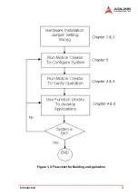
Page 17: ...Introduction 3 Figure 1 3 Flowchart for Building an Application ...
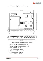
Page 26: ...12 Installation 2 2 PCI 8372 8366 Outline Drawing Figure 2 1 PCI 8372 8366 Mechanical Drawing ...
Page 31: ...Installation 17 2 Press HPI boot ...
Page 32: ...18 Installation 3 Press Flash DL button and select a kernel4 hex ...
Page 34: ...20 Installation Figure 2 3 SSCNET Communication Test Utility ...
Page 49: ...Signal Connections 35 Figure 3 9 Skin Type ...
Page 144: ...130 Operation Theory ...
Page 149: ...Motion Creator 135 Figure 5 6 Software Version Information ...
Page 160: ...146 Motion Creator Figure 5 13 Channel Selection Frame Figure 5 14 Motion Frame ...


