background image

26

Getting Started

Matrix MXE-5000 Series

User’s Manual

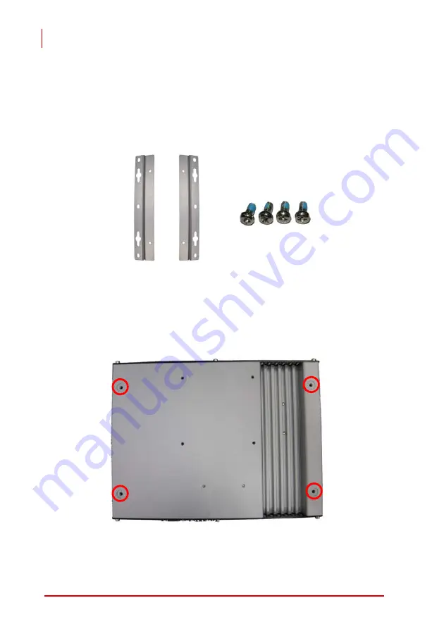
3.4 Mounting MXE-5104M using wall-mount kit

The MXE-5104M controller is shipped with a wall-mount kit allow-

ing the controller to be mounted on a vertical surface.
A pair of wall-mount brackets and 4 M4 screws are included in the

package.

1. Turn the system upside down and locate the 4 screw

holes.


Summary of Contents for Matrix MXE-5000 Series

Page 1: ...Advance Technologies Automate the World Manual Revision 2 00 Revision Date April 1 2011 Part Number 50 1Z075 2000 Matrix MXE 5000 Series MXE 5104M User s Manual ...

Page 2: ...Matrix MXE 5000 Series User s Manual ii Revision History Revision Release Date Description of Change s 2 00 2011 04 01 Initial release ...

Page 3: ...O Connectors 6 2 2 1 Power Button 7 2 2 2 Reset Button 7 2 2 3 LED Indicators 7 2 2 4 USB 2 0 Connectors 8 2 2 5 DVI connector 8 2 3 Rear Panel I O Connectors 8 2 3 1 DC Power Supply Connectors 9 2 3 2 COM Ports 10 2 3 3 Gigabit Ethernet 10 2 4 Internal I O Connectors 13 2 4 1 SATA Connectors 13 2 4 2 Clear CMOS Jumper 14 2 4 3 Jumper Setting for COM3 and COM4 15 3 Getting Started 17 3 1 Replacing...

Page 4: ... 2 4 Hardware Health Configuration 30 4 2 5 ACPI Configuration 30 4 2 6 USB Configuration 30 4 3 Chipset 31 4 3 1 Northbridge Configuration 31 4 3 2 Southbridge Configuration 32 4 4 Security 33 4 5 Boot 34 4 5 1 Boot Settings Configuration 34 4 5 2 Boot Device Priority 35 4 6 Exit 36 5 Driver Installation 37 5 1 Install the Chipset Driver 37 5 2 Install the Graphics Driver 38 5 3 Install the Ether...

Page 5: ...ble 2 1 LED Indicators 8 Table 2 2 D sub 9P signal name of COM1 COM4 ports 10 Table 2 3 Active Link LED 12 Table 2 4 Speed LED 12 Table 2 5 Clear CMOS Jumper 14 Table 4 1 Legacy USB support 31 Table 4 2 DVMT Mode Select 32 Table 4 3 Restore On Power Loss 32 Table 4 4 User Access Level 33 Table 4 5 Password Check 34 ...

Page 6: ...vi List of Tables Matrix MXE 5000 Series User s Manual This page intentionally left blank ...

Page 7: ...ility of such damages Trademarks Borland C C and Delphi are registered trademarks of the Borland Software Corporation Intel is a registered trademark of Intel Corporation LabVIEW is a trademark of National Instruments Corporation Linux and the Linux Logo are registered trademarks of Linus Torvalds MATLAB and the MATLAB Logo are registered trademarks of The MathWorks Inc Microsoft MS DOS Windows 95...

Page 8: ...h com ADLINK Technology China Co Ltd Address Ϟ Ꮦ ϰᮄऎᓴ 催 ᡔುऎ㢇 䏃 300 ো 201203 300 Fang Chun Rd Zhangjiang Hi Tech Park Pudong New Area Shanghai 201203 China Tel 86 21 5132 8988 Fax 86 21 5132 3588 Email market adlinktech com ADLINK Technology Beijing Address ҀᏖ ऎϞഄϰ䏃 1 োⲜ ࡼ ॺ E ᑻ 801 ᅸ 100085 Rm 801 Power Creative E No 1 B D Shang Di East Rd Beijing 100085 China Tel 86 10 5885 8666 Fax 86 10 5885 86...

Page 9: ... Tokyo 101 0045 Japan Tel 81 3 4455 3722 Fax 81 3 5209 6013 Email japan adlinktech com ADLINK Technology Inc Korean Liaison Office Address 昢殾柢 昢爎割 昢爎壟 1506 25 穢壊 B D 2 猻 2F Hando B D 1506 25 Seocho Dong Seocho Gu Seoul 137 070 Korea Tel 82 2 2057 0565 Fax 82 2 2057 0563 Email korea adlinktech com ADLINK Technology Singapore Pte Ltd Address 84 Genting Lane 07 02A Cityneon Design Centre Singapore 34...

Page 10: ...x Matrix MXE 5000 Series User s Manual This page intentionally left blank ...

Page 11: ...ufacturing environments or vehi cles Fanless and cable free structure ensures extensive durability for long term usage The Matrix MXE 5000 series features the Intel Core 2 Duo P8400 2 26 GHz processor delivering ample performance with low power consumption The MXE 5000 also integrates versatile general purpose and dedicated I O features to support a wide variety of applications Combining rugged de...

Page 12: ...C to 24 VDC isolation wide range DC power input X Up to four 1000 100 10 Mbps Ethernet ports X Two RS 232 ports and two RS 232 422 485 ports X Six USB 2 0 ports X DVI I connector combining analog CRT and DVI D signals supporting dual displays Note Extending the operating temperature to 20 C to 70 C is optional and requires use of an industrial solid state drive storage device ...

Page 13: ...Interface Serial Port X 2x RS 232 COM1 COM2 by DB9 connectors X 2x RS 232 422 485 COM3 COM4 by DB9 con nectors Ethernet X 2x GbE ports Intel 82574L on back panel X 2x GbE port Realtek 8111C on back panel USB 6x USB 2 0 ports Power Supply DC Input X Built in 9 24 VDC isolation DC input X 3P pluggable connector with latch V GND V Storage Device SATA HDD On board SATA port for 2 5 HDD SSD installatio...

Page 14: ... Screw pack for wall mounting and HDD fixing X User s manual X ADLINK All in One DVD Note OEM version packaging may vary depending on customer requests The assigned controller and or peripheral modules may be pre installed and shipped with the chassis Inquire with your dealer for additional Environmental Operating Temper ature Standard 0 C to 55 C w extended option 20 C to 70 C w Industrial Grade ...

Page 15: ...nual 2 System Description This section describes the appearance and connectors of the MXE 5104M controllers including chassis dimensions front panel connectors rear panel connectors and internal IO connectors 2 1 Mechanical Views all dimensions are in mm ...

Page 16: ...h of the MXE 5000 series controllers have the same I O con nector configuration on the front panel This section describes the functions of these I O connectors A Power Button B Reset Button C LED Indicators D USB 2 0 connector x2 Type A E DVI connector F USB 2 0 connector x4 Type A A B C D E F ...

Page 17: ...command is issued via the operating sys tem or the power button depressed If the system crashes depressing the button for 5 seconds forces a system shutdown 2 2 2 Reset Button The reset button executes a hard reset for the MXE 5104M con troller Any pin like object can be used to depress the reset button 2 2 3 LED Indicators In addition to the LED of the power button three LED indicators are displa...

Page 18: ...e monitor 2 3 Rear Panel I O Connectors The MXE 5104M controller provides a standard use I O connector configuration on the rear panel The entire MXE 5104M controller features DC power input connector four D sub 9P connectors COM1 through COM4 and four Gigabit Ethernet RJ45 connec tors LAN1 through LAN4 LED indicator Color Description Watchdog WD Yellow Indicates the status of the watch dog timer ...

Page 19: ...nnector consists of three pins V chassis ground and V from right to left respec tively V and V pins enable DC power input and chassis ground pin allows grounding of the chassis for optimum EMC compatibil ity The DC power input of MXE 5104M controller accepts a volt age input range from 9 VDC to 24 VDC G DC IN connector H COM Port connector x4 I Gigabit Ethernet x4 WG82574L x2 RTL8111C x2 G H I ...

Page 20: ...ion only Please refer to section 2 5 for setting instructions for RS 232 422 485 jumpers of COM3 and COM4 ports Table 2 2 D sub 9P signal name of COM1 COM4 ports 2 3 3 Gigabit Ethernet The MXE 5104M series controller provides four Gigabit Ethernet ports on the rear panel including 2 each of Intel WG82574L and Realtek 8111C Gigabit Ethernet controllers PIN RS 232 RS 422 RS 485 1 DCD TXD422 485DATA ...

Page 21: ...Fully integrated ASF 2 0 functionality with on chip µc Z SMBus 2 0 master interface for ASF functionality Z Preboot eXecution Environment PXE flash interface support The Realtek 8111C Ethernet controller supports the following fea tures Z x1 PCI Express interface with 2 5 GHz signaling Z Advanced error reporting Z Message signaled interrupts Z TCP segmentation offload large send support Z 802 3x f...

Page 22: ...Link LED Table 2 4 Speed LED LED Color Status Description Yellow OFF Ethernet port is disconnected ON Ethernet port is connected with no activity Flashing Ethernet port is connected and active LED Color Status Description Green Orange OFF 10 Mbps Green 100 Mbps Orange 1000 Mbps ...

Page 23: ...controller provides a Gen 1 1 5Gbit s speed SATA port The SATA host controller supports both a legacy mode using I O space and AHCI mode using memory space This SATA connector is designed for installing a 2 5 inch hard disk drive HDD or solid state disk SSD The HDD or SSD must be installed into the SATA connector with a HDD bracket Please refer to Section 3 1 for an illustration of 2 5 inch HDD or...

Page 24: ...hen abnormal conditions prevent the MXE 5104M controller from booting the BIOS content stored in CMOS can be cleared to restore the default settings To clear the CMOS 1 shorten pin 2 and pin 3 of JP6 2 restore normal mode shorten pin 1 and pin 2 Table 2 5 Clear CMOS Jumper Normal Clear ...

Page 25: ...r s Manual 2 4 3 Jumper Settings for COM3 and COM4 COM3 and COM4 of the MXE 5104M controller support RS 232 RS 422 and RS 485 JP2 JP3 JP4 JP12 JP13 and JP14 enable the operation mode of COM3 and COM4 to be set Jumper set tings are shown in the Table ...

Page 26: ...16 System Description Matrix MXE 5000 Series User s Manual This page intentionally left blank ...

Page 27: ... Memory in the system In addition COM port jumper settings and MXE 5104M wall mount installation are also discussed 3 1 Replacing a Hard Disk Drive Before replacing the hard disk drive the front panel rear panel and bottom chassis must first be removed as follows 1 Use a 6 7 64 inch hex wrench to remove all 6 screws M3 hex socket from the front panel Remove the panel ...

Page 28: ...18 Getting Started Matrix MXE 5000 Series User s Manual 2 Remove the 6 screws from the rear panel and remove the panel ...

Page 29: ...Getting Started 19 Matrix MXE 5000 Series User s Manual 3 Turn the system upside down and lift the chassis ...

Page 30: ...20 Getting Started Matrix MXE 5000 Series User s Manual 4 Unplug the SATA cable from the SATA connector receptacle on the PCB ...

Page 31: ...Getting Started 21 Matrix MXE 5000 Series User s Manual 5 After the bottom chassis is removed the HDD bracket can be found fixed thereto Remove the 4 screws from the HDD bracket ...

Page 32: ...rted Matrix MXE 5000 Series User s Manual 6 The SATA cable must be unplugged prior to replace ment of a hard disk 4 M3 screws fasten a 2 5 HDD or SSD to the system bracket 7 Reverse all steps to reassemble the system ...

Page 33: ...User s Manual 3 2 Installing Memory Before installing RAM the front panel rear panel and bottom chassis must first be removed as instructed in steps 1 to 4 in Chapter 3 1 1 After the bottom chassis is removed the RAM slot can be seen as follows ...

Page 34: ...24 Getting Started Matrix MXE 5000 Series User s Manual 2 Insert a DDRII SODIMM RAM into the slot at an angle 3 Depress RAM until the latch catches and the RAM is securely fixed ...

Page 35: ...mpatible with the DC input Incompatibility will cause system damage The DC power input connector of the MXE 5104M controller is located on the rear panel It has three pins V chassis ground and V from right to left respectively The DC power input accepts input voltage as shown previously 1 Connect the DC power as shown in the Figure 2 Fix the DC connector using the 2 screws ...

Page 36: ...04M using wall mount kit The MXE 5104M controller is shipped with a wall mount kit allow ing the controller to be mounted on a vertical surface A pair of wall mount brackets and 4 M4 screws are included in the package 1 Turn the system upside down and locate the 4 screw holes ...

Page 37: ...ted 27 Matrix MXE 5000 Series User s Manual 2 Fix the bracket with the M4 screws 3 Prepare the surface for mounting according to the schematic 4 Mount the controller by seating the keyholes on the installed screws ...

Page 38: ...such as the CPU northbridge and southbridge are located on the top of the PCB These components directly contact the top cover via thermal pads Heat generated by the components is largely dissi pated therethrough To maximize efficiency of heat dissipation maintain a minimum of 2 inches 5 cm clearance on the top of the MXE 5104M controller ...

Page 39: ...ning Changing BIOS settings may lead to incorrect controller behavior and possible inability to boot In such a case Section 2 4 4 provides instruction on clearing the CMOS and restoring default settings 4 1 Main 4 1 1 System Time System Date Use this option to specify the system time and date Highlight Sys tem Time or System Date using the up or down Arrow keys Enter new values using the keyboard ...

Page 40: ...different serial ports to avoid resource conflict 4 2 4 Hardware Health Configuration The hardware health option allows users to monitor hardware sta tus including CPU temperature system temperature and system voltages Vcore 5V 3 3V 12V 1 8V 5VSB VBAT 4 2 5 ACPI Configuration High Performance Event Timer Enables or disables HPET feature 4 2 6 USB Configuration Legacy USB Support Legacy USB Support...

Page 41: ... mass storage device s If set to Auto USB devices smaller than 530MB will be emulated as Floppy and those greater than 530MB will remain as hard drives The Forced FDD option can be used to force a hard disk type drive to boot as FDD Ext ZIP Drive 4 3 Chipset 4 3 1 Northbridge Configuration Internal Graphics Mode Select Specify the size of system memory used by internal graphics device 8MB is recom...

Page 42: ... default option is VBIOS Default 4 3 2 Southbridge Configuration Restore On Power Loss Defines what state the computer enters when power is restored after a power loss The options for this value are Last State Power On and Power Off Table 4 3 Restore On Power Loss Option Description DVMT Mode The graphics chip will dynamically allo cate system memory as graphics mem ory according to system and gra...

Page 43: ...o specify the access level for users Change User Password Select Change User Password and press Enter And enter your password in the appearing message box as prompted The password is stored in NVRAM after setup com pletes Password Check This option appears after specifying Supervisor password Table 4 5 Password Check Option Description No Access Users are not allowed to access the BIOS setting Vie...

Page 44: ...ay If this option is specified as Enabled the system displays the message Press DEL to run Setup during POST Intel 82574L PXE ROM Disabled Enabled the Intel 82574L PXE ROM closes opens Intel lan PXE function Realtek 8111C PXE ROM Disabled Enabled the Realtek 8111C PXE ROM closes opens Intel lan PXE function Option Description Disabled Specify BIOS to perform all POST tests Enabled Specify BIOS to ...

Page 45: ... Boot Device Boot from CF card 1 Select Hard Disk Drives and press Enter 2 CF card is displayed with its identification string Specify it as 1st Drive 3 Go back to upper level and select CF card as 1st Boot Device Boot from USB CD DVD drive 1 Select USB Drives and press Enter 2 CD DVD drive is displayed with its identification string Specify it as 1st Drive 3 Go back to upper level and select CD D...

Page 46: ...ing BIOS setup Load Optimal Defaults Select this option to set all BIOS options to default settings The Optimal setting is designed for maximum system perfor mance but may not work best for all computer applications In particular do not use the Optimal Setup options if the computer encounters system configuration problems Load Failsafe Defaults Select this option to set all BIOS options to default...

Page 47: ...ivers Most of the standard I O device drivers have been included in Windows 2 Install the chipset driver 3 Install the graphics driver 4 Install the Ethernet driver 5 Install the WDT watchdog timer driver 5 1 Install the Chipset Driver This section describes installation of the chipset driver for the MXE 5104M controller The chipset driver outlines to the operating system how to configure the Inte...

Page 48: ...X Microsoft Windows XP 64 Bit Edition X Microsoft Windows XP to install the chipset driver for the MXE 5104M controller 1 Close any running application 2 Insert the ADLINK All in One DVD The chipset driver is located in the directory x Driver Installation Matrix MXE 5104M Chipset where x denotes the DVD ROM drive 3 Execute Setup exe and follow on screen instructions to complete the setup 4 After i...

Page 49: ... Windows Vista 32 X Microsoft Windows Vista Business 32 bit version X Microsoft Windows Vista Enterprise 32 bit version X Microsoft Windows Vista Home Basic 32 bit version X Microsoft Windows Vista Home Premium 32 bit version X Microsoft Windows Vista Ultimate 32 bit version To install the graphics driver 1 Close any running application 2 Insert the ADLINK All in One DVD The graphics driver is loc...

Page 50: ...nstructions to complete the setup 4 After installation completes reboot the system 5 4 Install the WDT Driver A WDT watchdog timer resets the system when the operating system or application is halted A typical use of a WDT starts and periodically resets the timer and when timer is expired the sys tem resets The WDT driver must be installed prior to program ming the WDT To install WDT driver for th...

Page 51: ...re mechanism to reset the system in case the operating system or an application halts After starting watchdog timer you need to periodically reset the watchdog timer in the application before the timer expires Once watchdog timer expires a hard ware generated signal is sent to reset the system To use the WDT function library for MXE 5000 series you need to include the header file WDT h and linkage...

Page 52: ...g timer function of MXE 5000 controller InitWDT must be called before the invocation of any other WDT function Supported controllers MXE 5000 Syntax C C BOOL InitWDT Parameters None Return code TRUE if watchdog timer is successfully initialized FALSE if watchdog timer is failed to initialize ...

Page 53: ...etWDT BYTE tick BYTE unit Parameters tick Specify the number of tick for watchdog timer A valid value is 1 255 unit Specify the timeout ticks of the watchdog timer Return codes TRUE if timeout value of watchdog timer is successfully set FALSE if timeout value of watchdog timer is failed to set Value Description 0 The unit of tick is second For example when you specify tick as 100 and unit as 0 the...

Page 54: ...invoked the countdown of watchdog timer starts Users should call ResetWDT or StopWDT before the expiration of watchdog timer or the system will be reset Supported controllers MXE 5000 Syntax C C BOOL StartWDT Parameters None Return codes TRUE if watchdog timer is successfully started FALSE if watchdog timer is failed to start ...

Page 55: ...watchdog timer to the initial timeout value specified in SetWDT function Users should call ResetWDT or StopWDT before the expiration of watchdog timer or the sys tem will be reset Supported controllers MXE 5000 Syntax C C BOOL ResetWDT Parameters None Return codes TRUE if watchdog timer is successfully reset FALSE if watchdog timer is failed to reset ...

Page 56: ...es User s Manual StopWDT Description Stop the watchdog timer Supported controllers MXE 5000 Syntax C C BOOL StopWDT Parameters None Return codes TRUE if watchdog timer is successfully stopped FALSE if watchdog timer is failed to stop ...

Reviews: