Board Interfaces
7
cPCI-R6500
3
Board Interfaces
This chapter illustrates the board layout, connector pin
assignments, and switch settings to familiarize users with the
cPCI-R6500.
3.1
cPCI-R6500 Board Layout
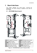
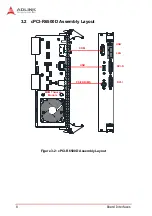
Figure 3-1: cPCI-R6500 Board Layout - Component Side
rJ1/2
CompactPCI connectors
COM1/2
Serial port box header
CN1
MXM connector
HDA1
Audio box header
CN4/5/6
SATA connectors
LAN1
LAN connectors (RJ-45)
CN3
Auxiliary Power connector
SW1
COM2 mode switch
CN9
Fan power connector
SW2/SW3
LAN switches
CN10
SATA Power connector
USB1
USB box header
CN9
CN4
CN5
CN6
PS/1
COM1
HDA1
USB1
COM2
CN3
CN10
rJ1
rJ2
SW3
SW1
SW2
CN1


