background image

Introduction

 3

cPCI-R6500

1.3

Block Diagram

Figure 1-1: cPCI-R6500 Functional Block Diagram


PCIE x4


TX, RX, GND


RS-232 10-pin box header

SATA 7-pin  connector

RS-232/422/485


SATA 0


MXM 3.0

PS/2 KB/MS

USB x1

LAN x2 (PICMG 2.16)

SATA 1/2


SATA 7-pin connector x2

HDA


LAN


Mic-in, Line-out Line-in, 

10-pin header

DVI-I


DVI-I


KB/MS 10-pin header


rJ5


rJ3


LAN

ALC262

L1     L2

PS/2 

KB/MS

USB x2


PS/2 KB/MS


10-pin box header

DB-9

USB

USB

USB

USB x2 10-pin header

Summary of Contents for cPCI-R6500 Series

Page 1: ...dvance Technologies Automate the World Manual Rev 0 10 Preliminary Revision Date October 23 2015 Part No 50 15084 1000 cPCI R6500 6U CompactPCI Rear Transition Module MXM Graphics Carrier User s Manua...

Page 2: ...ii Revision History Revision History Revision Release Date Description of Change s 0 10 2015 10 23 Preliminary release...

Page 3: ...ven if advised of the possibility of such damages Environmental Responsibility ADLINK is committed to fulfill its social responsibility to global environmental preservation through compliance with the...

Page 4: ...OTE NOTE Additional information aids and tips that help users perform tasks CAUTION Information to prevent minor physical injury component dam age data loss and or program corruption when trying to co...

Page 5: ...Contents 4 2 Specifications 5 2 1 cPCI R6500 General Specifications 5 2 2 I O Connectivity 6 2 3 GPU 6 3 Board Interfaces 7 3 1 cPCI R6500 Board Layout 7 3 2 cPCI R6500D Assembly Layout 8 3 3 cPCI R65...

Page 6: ...vi Table of Contents This page intentionally left blank...

Page 7: ...Block Diagram 3 Figure 2 1 cPCI R6500 General Specifications 6 Figure 3 1 cPCI R6500 Board Layout Component Side 7 Figure 3 2 cPCI R6500D Assembly Layout 8 Figure 3 3 cPCI R6501D Assembly Layout 9 Fig...

Page 8: ...viii List of Figures This page intentionally left blank...

Page 9: ...vity 6 Table 3 1 DVI I Connector Pin Definition 12 Table 3 2 DVI I Connector Pin Definition 13 Table 3 3 CompactPCI J3 Connector Pin Definition 20 Table 3 4 CompactPCI J5 Connector Pin Definition 21 T...

Page 10: ...x List of Tables This page intentionally left blank...

Page 11: ...6500 requires a compatible 6U Com pactPCI backplane with rear I O support and correctly configured CPU blade Three models are available the cPCI R6500D and cPCI R6501D 8HP for ATI MXM graphics modules...

Page 12: ...udio codec and Mic in Line in Line out via onboard 10 pin audio box header X Two DVI I ports for dual independent displays MXM graphics module dependent X One DB 9 serial port supporting RS 232 422 48...

Page 13: ...n box header SATA 7 pin connector RS 232 422 485 SATA 0 MXM 3 0 PS 2 KB MS USB x1 LAN x2 PICMG 2 16 SATA 1 2 SATA 7 pin connector x2 HDA LAN Mic in Line out Line in 10 pin header DVI I DVI I KB MS 10...

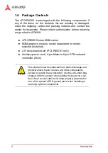
Page 14: ...graphics module model dependent on model selected installed X 2 5 drive bracket kit cPCI R6501D only X Auxiliary power cord 4 pin Molex to 6 pin RTM onboard connector 20cm CAUTION This product must b...

Page 15: ...ule 1x DB 9 COM port RS 232 422 485 1x PS 2 Mini DIN keyboard mouse cPCI R6501D 2x 10 100 1000BASE T Ethernet ports 1x USB 2 0 Type A ports 2x DVI I ports from MXM module cPCI R65N0D 2x 10 100 1000BAS...

Page 16: ...Extended Temperature 20 C to 70 C by screening Function cPCI R6500D cPCI R6501D cPCI R65N0 Faceplate Board Faceplate Board Faceplate Board LAN Y x2 Y x2 Y x2 USB Y x2 Y x2 Y x1 Y x2 Y x1 Y x1 box hea...

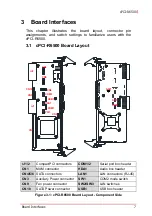
Page 17: ...re 3 1 cPCI R6500 Board Layout Component Side rJ1 2 CompactPCI connectors COM1 2 Serial port box header CN1 MXM connector HDA1 Audio box header CN4 5 6 SATA connectors LAN1 LAN connectors RJ 45 CN3 Au...

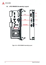
Page 18: ...8 Board Interfaces 3 2 cPCI R6500D Assembly Layout Figure 3 2 cPCI R6500D Assembly Layout PS 2 KB MS USB COM USB LAN DVI D DVI I MXM Thermal Module...

Page 19: ...Board Interfaces 9 cPCI R6500 3 3 cPCI R6501D Assembly Layout Figure 3 3 cPCI R6501D Assembly Layout MXM Thermal Module USB LAN DVI D DVI I 2 5 SATA Drive...

Page 20: ...10 Board Interfaces 3 4 cPCI R65N0 Assembly Layout Figure 3 4 cPCI R65N0 Assembly Layout USB LAN DVI D DVI I COM PS 2 KB MS MXM Thermal Module...

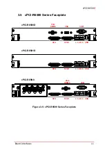
Page 21: ...PCI R6500 3 5 cPCI R6500 Series Faceplate Figure 3 5 cPCI R6500 Series Faceplate COM USB PS 2 KB MS DVI I DVI D a LAN b USB DVI I DVI D a LAN b USB PS 2 KB MS COM DVI I DVI D a LAN b USB cPCI R65N0 cP...

Page 22: ...0 3 TMDS Data2 4 Shield 18 TMDS Data0 4 TMDS Data4 19 TMDS Data0 5 Shield 5 TMDS Data4 20 TMDS Data5 6 DDC Clock SCL 21 TMDS Data5 7 DDC Data SDA 22 TMDS Clock Shield 8 Analog vertical sync 23 TMDS Cl...

Page 23: ...gnal Pin Signal 1 DVI_D_DAN2 16 DVI_D_HPD_L 2 DVI_D_DAP2 17 DVI_D_DAN0 3 GND 18 DVI_D_DAP0 4 NC 19 GND 5 NC 20 NC 6 DDCCLK_D 21 NC 7 DDCDATA_D 22 GND 8 NC 23 DVI_D_CLKP 9 DVI_D_DAN1 24 DVI_D_CLKN 10 D...

Page 24: ...4 LAN_TXP2 5 LAN_TXP2 6 RX LAN_TXN1 7 LAN_TXP3 8 LAN_TXN3 Status Speed LED Green Amber Activity LED Amber Network link is not established or system powered off OFF OFF 10 Mbps Link OFF ON Active OFF B...

Page 25: ...ly Pin RS 232 RS 422 RS 485 1 DCD TXD Data 2 RXD TXD Data 3 TXD RXD 4 DTR RXD 5 GND GND GND 6 DSR 7 RTS 8 CTS 9 RI NOTE NOTE See COM2 Mode Switches SW1 on page 22 Pin Signal Function 1 KB_DATA Keyboar...

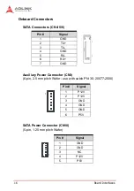
Page 26: ...ower Connector CN3 6 pin 2 5 mm pitch Wafer use with cable PN 30 20077 2000 SATA Power Connector CN10 5 pin 1 25 mm pitch Wafer Pin Signal 1 GND 2 TX 3 TX 4 GND 5 RX 6 RX 7 GND Pin Signal 1 P12V 2 P12...

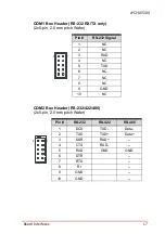
Page 27: ...0 mm pitch Wafer COM2 Box Header RS 232 422 485 2x5 pin 2 0 mm pitch Wafer Pin RS 232 Signal 1 NC 2 NC 3 RXD 4 NC 5 TXD 6 NC 7 NC 8 NC 9 GND 10 NC Pin RS 232 RS 422 RS 485 1 DCD TXD Data 2 TXD TXD Da...

Page 28: ...Keyboard Mouse Box Header PS 2 2x5 pin 2 0 mm pitch Wafer Pin Signal 1 GND 2 P12V 3 NC Pin Signal Pin Signal 2 L_OUT_L 1 GND 4 GND 3 L_OUT_R 6 L_IN_L 5 GND 8 GND 7 L_IN_R 10 MIC_LR 9 GND Pin Signal P...

Page 29: ...Board Interfaces 19 cPCI R6500 USB Box Header USB1 2x5 pin 2 0 mm pitch Wafer Pin Signal Pin Signal 2 5V 1 5V 4 USB4_D 3 USB7_D 6 USB4_D 5 USB7_D 8 GND 7 GND 10 NC 9 Key 2 1...

Page 30: ...ND 13 GND USB8P USB8N GND NC NC GND 12 GND NC NC GND USB7P USB7N GND 11 GND USB4P USB4N GND NC NC GND 10 GND USB OC4 L NC NC NC NC GND 9 GND CTS1 L RI1 L NC NC NC GND 8 GND SIN1 SOUT1 DTR1 L DSR1 L RT...

Page 31: ...NC GND SATA_TXP0 SATA_TXN0 GND 13 GND LAN1_100 L a LAN2_100 L b NC LAN2_1G L b LAN1_1G L a GND 12 GND NC NC NC NC NC GND 11 GND NC NC GND NC NC GND 10 GND NC NC GND NC NC GND 9 GND NC NC NC NC NC GND...

Page 32: ...port supports RS 232 422 485 modes Switch SW1 can be used to configure the COM2 port to the desired mode using the settings shown below set to RS 232 by default Table 3 5 COM2 Mode Switch Settings Se...

Page 33: ...e or to LAN a b on the face plate I O but not both simultaneously Switch SW2 can be used to route the LAN a signals and set to faceplate RJ 45 connectors by default Table 3 6 LAN Control Switch Settin...

Page 34: ...24 Board Interfaces This page intentionally left blank...

Page 35: ...Turn off power and unplug any power cords cables X To avoid electrical shock and or damage to equipment Z Keep equipment away from water or liquid sources Z Keep equipment away from high heat or high...

Page 36: ...iced by authorized technicians when Z The power cord or plug is damaged Z Liquid has penetrated the equipment Z It has been exposed to high humidity moisture Z It is not functioning or does not functi...

Page 37: ...300 Fang Chun Rd Zhangjiang Hi Tech Park Pudong New Area Shanghai 201203 China Tel 86 21 5132 8988 Fax 86 21 5132 3588 Email market adlinktech com ADLINK Technology Beijing Address 1 E 801 100085 Rm 8...

Page 38: ...o Dong Seocho Gu Seoul 137 070 Korea Tel 82 2 2057 0565 Fax 82 2 2057 0563 Email korea adlinktech com ADLINK Technology Singapore Pte Ltd Address 84 Genting Lane 07 02A Cityneon Design Centre Singapor...

Reviews: