


NEO FIRE – Technical Manual
29
2379Z05
ON
ON
53%
53%
53%
80%
40%
40%
80%
80%
80%
80%
80%
100%
100%
100%
OFF
OFF
53%
53%
53%
80%
80%
40%
40%
80%
20%
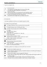
In this example, the boilers’activation and their power control would be made as shown below:
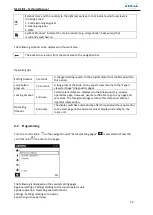
10.2
External control signal 0…10 V to regulate start-up and power modulation of each boiler
Each boiler can receive and process an external signal 0…10 V.
The external signal 0…10 V will transmit to the boiler a set-up temperature value.
The signal 0…10 V must be connected to the terminals shown inside the boiler.
The linear characteristic is defined by 2 fixed points. The setting uses 2 pairs of parameters for function value
and voltage value (F1/U1 and F2/U2).
Voltage
0,15V
U1=0V
U2=10V
Flow
temperature
setpoint
F2=85ºC
F2=65ºC
Summary of Contents for NEO FIRE 120
Page 1: ...TECHNICAL MANUAL OF INSTALLATION USE AND MAINTENANCE 07 2020 ...
Page 7: ...NEO FIRE Technical Manual 7 NEO FIRE 360 900 ...
Page 9: ...NEO FIRE Technical Manual 9 NEO FIRE 80 NEO FIRE 120 160 ...
Page 10: ...NEO FIRE Technical Manual 10 NEO FIRE 200 280 NEO FIRE 360 720 ...
Page 34: ...NEO FIRE Technical Manual 34 11 1 Electric drawing NEO FIRE 80 720 ...
Page 35: ...NEO FIRE Technical Manual 35 11 2 Electric drawing NEO FIRE 810 900 ...
Page 37: ...NEO FIRE Technical Manual 37 Electric drawing 1 Boiler with 3 heating circuits ...
Page 41: ...NEO FIRE Technical Manual 41 System drawing 1 Boiler and Domestic Hot Water DHWS ...
Page 58: ...NEO FIRE Technical Manual 58 System drawing D H W and heating circuit 11 11 ...
Page 59: ...NEO FIRE Technical Manual 59 System drawing of an old installation heating circuit 11 ...
Page 70: ...NEO FIRE Technical Manual 70 18 4 Position of probes and sensors ...


