OPERATING AND USER MANUAL Q-12 CoaXPress series
________________________________________________________________________________________________________________
_________________________________________________________________________________________
Adimec
14
4.2.3 Adimec Service Port
The Adimec Service Port (ASP) interface is available for firmware uploads to the camera.
USB driver XR21x141x is required to support communication via the ASP port.
The USB connection will be available as a virtual COM port.
4.2.4 I/O Connector
A trigger input and flash strobe output are available at the I/O connector. The input and output are galvanic
isolated from the internal camera electronics by means of an optocoupler (Avago ACPL-M50L).
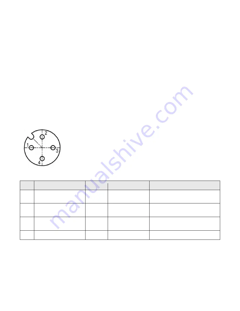
The connector layout is shown in Figure 4-2 with the pin description in Table 4-5.
Table 4-6 lists the recommended resistor values to be used in the termination circuitry to achieve the
recommended currents. In Figure 4-3 the recommended termination circuitry is shown.
NOTE:
Opto-couplers require a certain response time to turn on or to turn off, i.e. to switch from the non-
conductive state to the conductive state or the other way around. This response time depends on the used
electronic circuit. For the “trigger in” it can be as short as < 0.5 µs. For the “flash strobe out” it can be as short as
< 2 µs. In practice this response time means that when a trigger is applied there will be a delay between the
rising edge of the trigger and the reaction of the camera.
Figure 4-2: Female I/O connector layout viewed from the backside of the camera
Table 4-5: Connector pinning
Pin
Signal name
Type
Level
Description
1
Trigger in
Input
10..20 mA (
10 mA
recommended)
Anode of opto-coupler
*
2
Flash strobe out
Output
2.5 mA
Recommended
Open collector of opto-coupler photo
transistor.
3
Flash strobe return
Output
Isolated gnd
Emitter of opto-coupler photo
transistor.
4
Trigger return
Input
Isolated gnd
Cathode of opto-coupler
*
serial resistors 2x 220
Ω inside camera.


