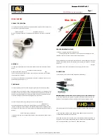
Magna BluePirat Remote, User Manual
The Magna BluePirat Remote is a cutting-edge device that revolutionizes your TV viewing experience. This compact, user-friendly remote offers seamless control over your television and various smart devices. Ensure optimum functionality with our comprehensive user manual, available for free download exclusively at manualshive.com.
Share
Download


Reviews:
No comments
Related manuals for BluePirat Remote

Smart C1640W
Brand: GE Pages: 76

C1440W
Brand: GE Pages: 76

C1033
Brand: GE Pages: 78

C1033
Brand: GE Pages: 78

A835
Brand: GE Pages: 106

C1440W
Brand: GE Pages: 76
RE-BCC8FDM
Brand: DSE Pages: 4

DiMAGE G500
Brand: Konica Minolta Pages: 126

QDSP-208C
Brand: Quanmax Pages: 38
DS1-MP10RX2
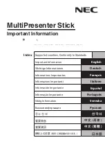
Brand: NEC Pages: 204

DIGIFRAME 1960
Brand: Braun Pages: 70

Date
Brand: Pentax Pages: 36

Mobile-I
Brand: OiTEZ Pages: 8

Pantera TF 6M8
Brand: Dalsa Pages: 68

SD19 MagiCam
Brand: PNJcam Pages: 36

PX-10E
Brand: Elmo Pages: 86

QCW4MP1PT-AU
Brand: Q-See Pages: 22

SIP1201
Brand: KaiCong Pages: 47


