background image


Industrial


Electronic Devices 


 ADFweb.com Srl – IT31010 – Mareno – Treviso                                                      INFO:  

www.adfweb.com

      Phone +39.0438.30.91.31            


User Manual   

OPC UA Client / CAN 


Document code: MN67B12_ENG     Revision 1.000    Page 9 of 32


LEDS: 

 
The device has got five LEDs that are used to give information of the functioning status. 
The various meanings of the LEDs are described in the table below. 


LED 

Normal Mode 

Boot Mode 

1: Device State (green) 

Blinks slowly (~1Hz) 

Blinks quickly: 

Boot state  

Blinks very slowly (~0.5Hz): 

update in progress 

2: OPC UA comm. (yellow) 

Flashing:

 OPC UA response 

OFF:

 No OPC UA response 

Blinks quickly:

 Boot state 

Blinks very slowly (~0.5Hz):

 update in progress 

3: CAN comm. (yellow) 

Flashing:

 CAN message 

OFF:

 No CAN messages 

Blinks quickly:

 Boot state 

Blinks very slowly (~0.5Hz):

 update in progress 

4: Error state (yellow) 

ON:

 At least one OPC UA Server is disconnected 

OFF:

 all OPC UA Servers are connected 

Blinks quickly:

 Boot state 

Blinks very slowly (~0.5Hz):

 update in progress 

5: Link Ethernet (green) 

ON:

 Ethernet cable connected 

OFF:

 Ethernet cable disconnected 

ON:

 Ethernet cable connected 

OFF:

 Ethernet cable disconnected 


Summary of Contents for HD67B12-B2

Page 1: ...www adfweb com Product HD67B08 Serial www adfweb com Product HD67B09 Modbus Slave www adfweb com Product HD67B10 Modbus TCP Slave www adfweb com Product HD67B11 BACnet www adfweb com Product HD67B13 CANopen www adfweb com Product HD67B14 DeviceNet Slave www adfweb com Product HD67B15 DMX www adfweb com Product HD67B16 EtherNet IP Slave www adfweb com Product HD67B17 J1939 www adfweb com Product HD...

Page 2: ...TIES AND TECHNICAL SUPPORT 32 RETURN POLICY 32 Pagina 2 di 32 UPDATED DOCUMENTATION Dear customer we thank you for your attention and we remind you that you need to check that the following document is Updated Related to the product you own To obtain the most recently updated document note the document code that appears at the top right hand corner of each page of this document With this Document ...

Page 3: ... etc QUALIFIED PERSONNEL The device can be used only by qualified personnel strictly in accordance with the specifications Qualified personnel are persons who are familiar with the installation assembly commissioning and operation of this equipment and who have appropriate qualifications for their job RESIDUAL RISKS The device is state of the art and is safe The instruments can represent a potenti...

Page 4: ...ial Electronic Devices ADFweb com Srl IT31010 Mareno Treviso INFO www adfweb com Phone 39 0438 30 91 31 User Manual OPC UA Client CAN Document code MN67B12_ENG Revision 1 000 Page 4 of 32 EXAMPLE OF CONNECTION ...

Page 5: ...ces ADFweb com Srl IT31010 Mareno Treviso INFO www adfweb com Phone 39 0438 30 91 31 User Manual OPC UA Client CAN Document code MN67B12_ENG Revision 1 000 Page 5 of 32 Figure 1 Connection scheme for HD67B12 B2 CONNECTION SCHEME ...

Page 6: ...es in reading and 1500 bytes in writing Two directional information between CAN and OPC UA Mountable on 35mm Rail DIN Wide power supply input range 8 24V AC or 12 35V DC Wide temperature range 40 C 85 C 40 F 185 F CONFIGURATION You need Compositor SW67B12 software on your PC in order to perform the following Define the parameter of OPC UA Define the parameter of CAN line Define the list of OPC UA ...

Page 7: ... Client CAN Document code MN67B12_ENG Revision 1 000 Page 7 of 32 POWER SUPPLY The devices can be powered between a wide range of tensions For more details see the two tables below VAC VDC Vmin Vmax Vmin Vmax HD67B12 B2 8V 24V 12V 35V Consumption at 24V DC Device W VA HD67B12 B2 4 Caution Not reverse the polarity power HD67B12 B2 ...

Page 8: ...ice has got two functions mode depending of the position of the Dip1 of Dip Switch A The first with Dip1 in Off position factory setting is used for the normal working of the device The second with Dip1 in On position is used for upload the Project Firmware For the operations to follow for the updating see UPDATE DEVICE section According to the functioning mode the LEDs will have specifics functio...

Page 9: ...oot state Blinks very slowly 0 5Hz update in progress 2 OPC UA comm yellow Flashing OPC UA response OFF No OPC UA response Blinks quickly Boot state Blinks very slowly 0 5Hz update in progress 3 CAN comm yellow Flashing CAN message OFF No CAN messages Blinks quickly Boot state Blinks very slowly 0 5Hz update in progress 4 Error state yellow ON At least one OPC UA Server is disconnected OFF all OPC...

Page 10: ...evision 1 000 Page 10 of 32 CAN For terminating the CAN line with a 120Ω resistor it is necessary that the Dip1 of Dip Switch A is at ON position Cable characteristics DC parameter Impedance 70 Ohm m AC parameters Impedance 120 Ohm m Delay 5 ns m Length Baud Rate bps Length MAX m 10 K 5000 20 K 2500 50 K 1000 100 K 650 125 K 500 250 K 250 500 K 100 800 K 50 1000 K 25 ...

Page 11: ...he Ethernet connection must be made using Connector3 of HD67B12 B2 with at least a Category 5E cable The maximum length of the cable should not exceed 100m The cable has to conform to the T568 norms relative to connections in cat 5 up to 100 Mbps To connect the device to an Hub Switch is recommended the use of a straight cable to connect the device to a PC PLC other is recommended the use of a cro...

Page 12: ...se the available software that runs with Windows called SW67B12 It is downloadable on the site www adfweb com and its operation is described in this document This manual is referenced to the last version of the software present on our web site The software works with MSWindows XP Vista Seven 8 10 32 64bit When launching the SW67B12 the window below appears Fig 2 Note It is necessary to have instal...

Page 13: ...contains the entire device s configuration A device s configuration can also be imported or exported To clone the configurations of a programmable OPC UA Client CAN Converter in order to configure another device in the same manner it is necessary to maintain the folder and all its contents To clone a project in order to obtain a different version of the project it is sufficient to duplicate the pr...

Page 14: ... is the possibility to change the language of the software and check the updatings for the compositor In the section Language it is possible to change the language of the software In the section Connection Options it is possible to check if there are some updatings of the software compositor in ADFweb com website Checking the option Check Software Update at Start of Program the SW67B12 check autom...

Page 15: ...one 39 0438 30 91 31 User Manual OPC UA Client CAN Document code MN67B12_ENG Revision 1 000 Page 15 of 32 In the section Software Settings it is possible to enable disable some keyboard s commands for an easier navigation inside the tables contained in the different sections of the software ...

Page 16: ...ed In the field SubNet Mask the SubNet Mask for OPC UA side of the converter is defined In the field Gateway the default gateway of the net is defined This feature can be enabled or disabled pressing the Check Box field This feature is used for going out of the net In the field DNS the IP Address of the DNS server is defined This feature can be enabled or disabled pressing the Check Box field The ...

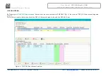
Page 17: ... CAN Document code MN67B12_ENG Revision 1 000 Page 17 of 32 Figure 4 OPC UA Client Access window OPC UA ACCESS By Pressing the OPC UA Client Access button from the main window for SW67B12 Fig 2 the window OPC UA Client Access appears Fig 4 This section is used to define the list of the OPC UA Servers to read write with the OPC UA Client ...

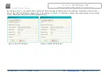
Page 18: ...age 18 of 32 Figure 5 Add OPC UA Server Figure 6 Modify OPC UA Server By clicking on Add it is possible to add a new OPC UA Server inserting its characteristics Server Address Authorization Security Type The window Add OPC UA Server appears Fig 5 By clicking on Modify it is possible to change these characteristics for the selected Server The window Modify OPC UA Server appears Fig 6 ...

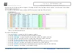
Page 19: ...UA window By clicking on Scan it is possible to get the list of available variables from the selected Server The window Scan Server OPC UA appears Fig 7 The means of the checkboxes inside the table are If the field Read is checked the variable can be read If the field Write is checked the variable can be written Note For each variable it is possible to uncheck these fields and the variable will no...

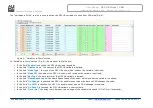
Page 20: ... field Enable is checked the OPC UA variable is enabled In the field Display name the name of the OPC UA variable is defined In the field Node Type the type of the OPC UA node which includes the variable is defined In the field Node ID the name of the OPC UA node which includes the variable is defined In the field Var Type the data format of the OPC UA variable is defined In the field Name Space I...

Page 21: ...ed In the field Node Type the type of the OPC UA node which includes the variable is defined In the field Node ID the name of the OPC UA node which includes the variable is defined In the field Var Type the data format of the OPC UA variable is defined In the field Name Space Index the Name Space Index of the node which includes the variable is defined If the field On Change is checked the OPC UA ...

Page 22: ... the starting byte of the internal memory arrays where getting the value is defined In the field Mnemonic a description of the variable is defined Note By clicking on Auto Pos the position of the internal memory arrays where saving getting the value of variable is automatically calculated Note A variable can be added manually in Variables in Read and or Variables in Write sections without scanning...

Page 23: ...of CAN packet use for the Cob ID is defined 2 0A 11 bits or 2 0B 29 bits In the field Dimension the number of byte of the COB from 1 to 8 is defined The field TimeOut is used for put at zero the data into OPC UA if the CAN frame doesn t arrive with a frequency less than the time expressed in the field If the value in the field is 0 it means that you don t want to use this In the field Byte1 insert...

Page 24: ... the internal memory array where saving 5th byte of the CAN message In the field Byte6 insert the byte of the internal memory array where saving 6th byte of the CAN message In the field Byte7 insert the byte of the internal memory array where saving 7th byte of the CAN message In the field Byte8 insert the byte of the internal memory array where saving 8th byte of the CAN message In the field Mnem...

Page 25: ...defined 2 0A 11 bits or 2 0B 29 bits In the field Dimension the number of byte of the COB from 1 to 8 is defined If the field OnChange is checked the frame is sent when the data from OPC UA change If the field OnCMD is checked the frame is sent when a OPC UA message is received If the field OnTimer is checked the frame is sent cyclically with the delay defined in the field Time expressed in ms In ...

Page 26: ...ternal memory array where taking 5th byte of the CAN message In the field Byte6 insert the byte of the internal memory array where taking 6th byte of the CAN message In the field Byte7 insert the byte of the internal memory array where taking 7th byte of the CAN message In the field Byte8 insert the byte of the internal memory array where taking 8th byte of the CAN message In the field Mnemonic it...

Page 27: ...N the device Connect the Ethernet cable Insert the IP 192 168 2 205 Select which operations you want to do Press the Execute update firmware button to start the upload When all the operations are OK turn OFF the Device Put Dip1 of Dip Switch A in OFF position Turn ON the device If you know the actual IP address of the device you have to use this procedure Turn ON the Device with the Ethernet cable...

Page 28: ...settings If you are using the program inside a Virtual Machine try to use in the main Operating System If you are using Windows Seven Vista 8 or 10 make sure that you have the administrator privileges In case you have to program more than one device using the UDP Update you have to cancel the ARP table every time you connect a new device on Ethernet For do this you have to launch the Command Promp...

Page 29: ...b com Srl IT31010 Mareno Treviso INFO www adfweb com Phone 39 0438 30 91 31 User Manual OPC UA Client CAN Document code MN67B12_ENG Revision 1 000 Page 29 of 32 MECHANICAL DIMENSIONS Figure 14 Mechanical dimensions scheme for HD67B12 B2 ...

Page 30: ...ing part number is formed by a valid combination of the following HD67B12 B 2 Connectors Type 2 Fixed Screw Terminal Enclosure Type B Modulbox 4M 35mm DIN Rail mounting Device Family HD67B12 OPC UA Client CAN Converter Order Code HD67B12 B2 OPC UA Client CAN Converter ACCESSORIES Order Code AC34011 35mm Rail DIN Power Supply 220 240V AC 50 60Hz 12 V DC Order Code AC34012 35mm Rail DIN Power Supply...

Page 31: ...ountries with separate collection systems This symbol on the product or on its packaging indicates that this product may not be treated as household rubbish Instead it should be taken to an applicable collection point for the recycling of electrical and electronic equipment If the product is disposed correctly you will help prevent potential negative environmental factors and impact of human healt...

Page 32: ... exchange or repair it please do the following Obtain a Product Return Number PRN from our internet support at www adfweb com Together with the request you need to provide detailed information about the problem Send the product to the address provided with the PRN having prepaid the shipping costs shipment costs billed to us will not be accepted If the product is within the warranty of twelve mont...

Reviews: