background image

FR

FR

EN

FIELD TEST DEVICE - LoRaWAN US 902-928 - Mode d'emploi V1.0.0

11

Page

of 27

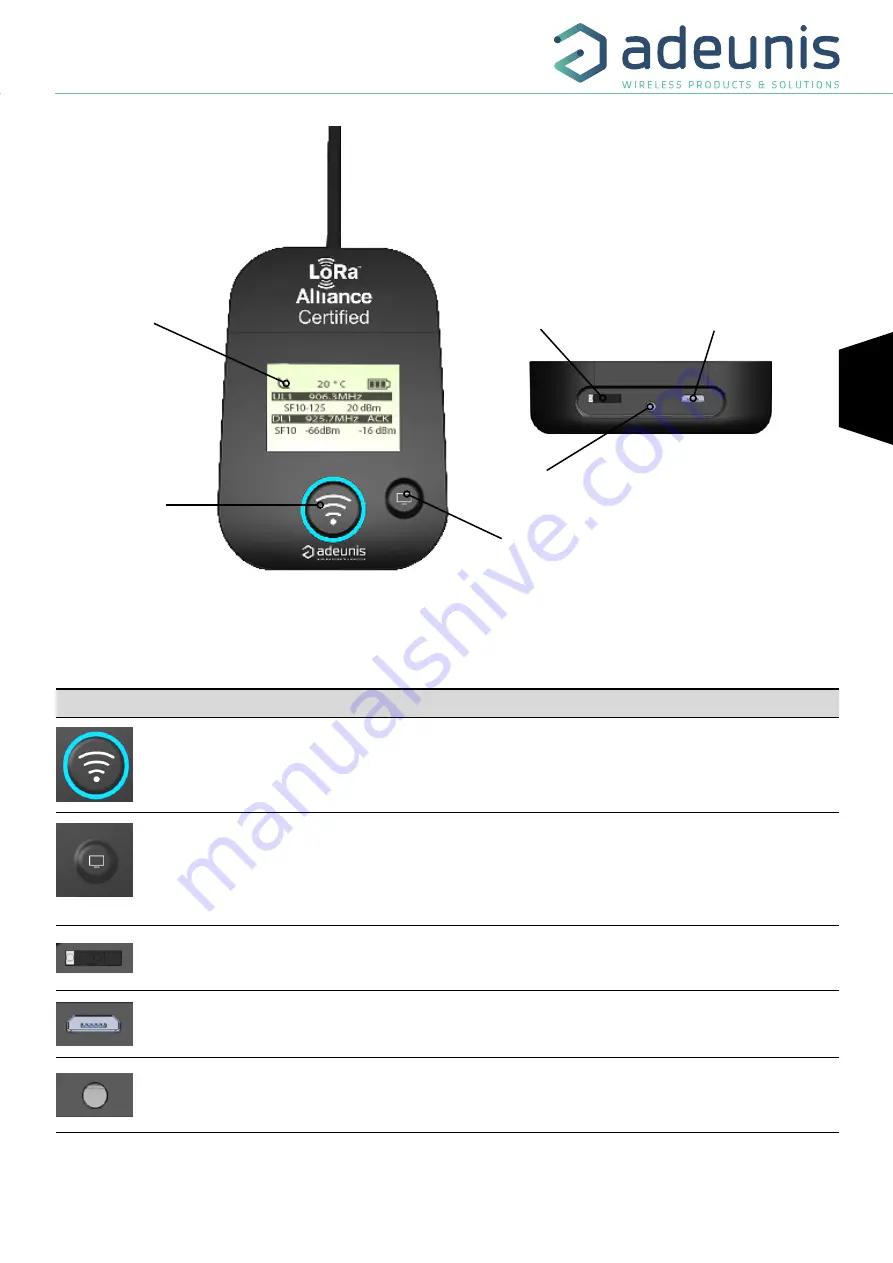
LCD screen

Push button 1

Push button 2

Figure 3 : Front view

ON/OFF switch 

Charge indicator

Micro USB connector 

2.2.  Button description


Interface operation

Pushbutton 1

This button allows you to carry out radio transmissions in manual mode. In the PER menu, a long 
press will allow you to reset the counters to zero.

Pushbutton 2

This button allows you to manage the LCD screen.
When the LCD backlight is switched off, pressing this button will switch on the backlight.
When the LCD backlight is switched on, each press will allow you to scroll through the different 
screens available on this device.

ON/OFF Switch

The ON/OFF switch allows you to switch the device on or off. Moving the switch to the right will turn 
the device on.

Micro-USB connector

The micro-USB connector allows you to charge the device (see paragraph 1.4) or configure it (see 
paragraph 3). 

Charge indicator

The charge LED shows you the device’s charge status (see paragraph 1.4).

Figure 4 : rear view

2. DEVICE DESCRIPTION

2.1.  User interface

Summary of Contents for LoRaWAN US 902-928

Page 1: ...Adeunis 283 rue Louis Néel Parc Technologique Pré Roux 38920 CROLLES France www adeunis com FIELD TEST DEVICE LoRaWAN US 902 928 Guide utilisateur User Guide Version V1 0 0 ...

Page 2: ...ICE DESCRIPTION 11 2 1 User interface 11 2 2 Button description 11 3 SCREEN DESCRIPTION 12 3 1 Start Screen 12 3 2 Join Screen 12 3 3 Uplink Downlink screen 13 3 4 GPS screen 14 3 5 PER Packet Error Rate screen 14 3 6 Downlink screen 15 4 DECODING THE PAYLOAD 16 4 1 Frame 1 description 16 4 2 Frame 2 description 17 5 DEVICE CONFIGURATION 19 5 1 Connecting the device to a computer 19 5 2 Command mo...

Page 3: ...d un droit de propriété intellectuelle No part of this document may be reproduced or transmitted in electronic or paper or photocopying without the agreement adeunis This document may be changed without notice All trademarks mentioned in this guide are the subject of intellectual property rights adeunis Kein Teil dieses Dokuments darf reproduziert oder übertragen werden in elektronischer oder Papi...

Page 4: ... all rights to this document and the information contained herein Reproduction use or disclo sure to third parties without express permission is strictly prohibited Copyright 2016 adeunis adeunis is a registered trademark in the EU and other countries TECHNICAL SUPPORT Website Our website contains a lot of useful information information on modules and wireless modems user guides and configuration s...

Page 5: ...rmful interference to radio or television reception which can be determined by turning the equipment off and on the user is encouraged to try to correct the interference by one or more of the following measures Reorient or relocate the receiving antenna Increase the separation between the equipment and receiver Connect the equipment into an outlet on a circuit different from that to which the rece...

Page 6: ... without notice in writing and urges its customers to make sure that the information they have is valid adeunis configuration software and programs are available free of charge in a non modifiable version adeu nis can make no guarantees including guarantees concerning suitability and applicability for a certain type of application Under no circumstances can the manufacturer or the distributor of an ...

Page 7: ... incorrect type Please note Do not install the equipment close to a heat source or in damp conditions Please note When the equipment is open do not carry out any operations other than the ones set out in this document Please note Do not open the product as there is a risk of electrical shock Please note For your own safety you must ensure that the equipment is switched off before carrying out any w...

Page 8: ...his symbol on the product or on its packaging indicates that this product must not be disposed of with your other household waste Instead it is your responsibility to dispose of your waste by taking it to a collection point designated for the recycling of electrical and electronic appliances Separate collection and recycling of your waste at the time of disposal will contribute to conserving natur...

Page 9: ...nstantly view the results Equipped with a large LCD screen you can view various information relating to how the network being used is functioning Uplink Downlink SF PER etc in addition to information from sensors GPS coordinates temperature battery level etc This device is specifically adapted for application validation such as communicating sensors tracking smart building metering security and M2...

Page 10: ...evice configuration Via AT commands see relevant chapter to find a full list of available AT commands Serial rate 115 2 kbps Parity None Amount of data 8 Stop bit 1 Functioning temperature 30 C 70 C Network settings Applicative port Downlink 1 1 4 Charging the FTD The device is equipped with a rechargeable battery Once the device has been connected to a USB charger or the USB socket of a computer ...

Page 11: ...e the LCD screen When the LCD backlight is switched off pressing this button will switch on the backlight When the LCD backlight is switched on each press will allow you to scroll through the different screens available on this device ON OFF Switch The ON OFF switch allows you to switch the device on or off Moving the switch to the right will turn the device on Micro USB connector The micro USB co...

Page 12: ... of the device Once it has been switched on the device s LCD screen will light up and the start menu will be displayed This screen show the 2 firmware versions during few seconds NOTE If the device does not switch on this could mean that there is insufficient battery charge You would then need to connect the device to a USB charger When the battery is completely empty it is possible that the devic...

Page 13: ...mission Status Second on the left No icon There is currently no radio transmission Manual transmission has been triggered transmission cycle in progress Periodic transmission has been triggered transmission cycle in progress Uplink information Black Line Display showing the number of Uplink UL1 to UL8 frame repetitions as well as the transmission frequency of the frame accurate to one decimal plac...

Page 14: ...DE Display showing latitude coordinates in degrees minutes and seconds LONGITUDE Display showing longitude coordinates in degrees minutes and seconds When GPS has not yet been fixed no information on latitude or longitude will be displayed on the screen and the information icon will indicate that GPS has not been synchronized Figure 10 GPS screen No synchronisation If the device falls out of synch...

Page 15: ...TANT in this menu a long press in the button 1 will allow you to reset the counters to zero 3 6 Downlink screen This menu can be accessed by briefly pressing on pushbutton 2 after the PER menu It will allow you to view a downlink frame sending by the network This frame is displayed in ASCII characters The non printable characters are replace by a point The screen allow a viewing of 51 characters 1...

Page 16: ...nsmission mode no bouton pressed no accelerometer only the first byte status byte is sent and its value will be 0x00 4 1 1 Status For frame 1 using the previous example the value of status byte is 0x30 i e 0011 0000 in binary so in the table Hex Binary Comments 30 0 Not used 0 Transmission triggered by the accelerometer 1 Transmission triggered by pressing pushbutton 1 1 Presence of GPS informatio...

Page 17: ...vice s LCD screen 4 1 4 GPS quality Not available in Legacy mode Hex Value Frame N Byte N Bit N Comments Value 27 2 1 10 7 4 Reception scale 1 Good 2 Average 3 Poor 7 3 0 Number of satellites 1 16 The byte s MSB allows you to find out the quality of the GPS signal The byte s LSB allows you to find out the number of satellites viewed by the device 4 2 Frame 2 description Information will always be ...

Page 18: ...k frame counter but an internal frame counter Therefore there is no correlation between this counter and the one that you can view on the network 4 2 3 DL counter Hex Decimal Frame N Byte N Comments Value 20 32 2 4 Downlink frame counter 0 255 Please note This counter is not the LoRaWAN stack frame counter but an internal frame counter Therefore there is no correlation between this counter and the...

Page 19: ...nput of a computer The FTD device has a Type B micro USB connector During connection the device must be recognised by the computer as a Virtual Com Port VCP device Using Windows Verification that the device has been recognized to be functioning properly can be obtained by consulting the device manager You should see the USB series device with a corresponding COM port number appear during connectio...

Page 20: ...e Click on the Open button to open the serial port PLEASE NOTE If the com port has been opened correctly Hercules will display the message Serial COM3 port opened Alternatively Serial port com opening error will be displayed meaning either that the com port is already open for another application or it does not exist To supply power to the device move the switch to the right Switch ON OFF Bottom v...

Page 21: ...en received the modem will feedback cr lf Data for ATS type playback control n AT S or AT V O cr lf for any other command when this has been accepted E cr lf if it refuses the command due to a syntax error unknown command unknown range invalid parameter etc CM cr lf if it accepts the input in command mode Table of AT commands Command Description Response ATS n Feeds back the content of the n range...

Page 22: ...irst time the device has been switched on or if this configuration has not been changed ATS n m or ATR type modification commands allow you to modify the content of these ranges It is essential to save the parameters using the AT W command before exiting the command mode otherwise all of your changes will be lost IMPORTANT The registers that are not documented that can appear in the list following...

Page 23: ...he device s independence This mode should be used for static use fixed position or very slow movement or where satellite visibility is very good The user can also choose to reset the GPS once it is switched on This operation will allow you to delete the GPS memory as well as all previous ly acquired information This can be useful when the GPS is not able to synchronize itself while it is starting ...

Page 24: ...55654 WARNING The register need to be completed with zero to send a byte or the product will completed by himself the register and you will not have the result you would like to have Example with ATS385 1 ATS386 AB000000 The system understand the frame AB000000 and send the first byte You will receive AB ATS386 AB The system understand the frame 000000AB and send the first byte You will receive 00...

Page 25: ...1 Use the chan nels 0 7 in 125 kHz and a channel 65 in 500 kHz 8 the device will use only Band n 8 Use the chan nels 56 63 in 125 kHz and 71 in 500 kHz S280 NETWORK ID 0 S281 DEVICE ADDRESS 0 S214 and S215 LORA APP_EUI The S214 and S215 ranges determine the APP_EUI key used during the JOIN phase in OTAA mode The key is made up of 16 characters spread across these 2 ranges which can each contain 8 ...

Page 26: ...Data Rate DR value Description NWK_sKEY Network session key APP_sKEY Application session key DEVICE ADDRESS Network device address S222 à S225 LORA NWK_sKEY The ranges from S222 to S225 determine the NWK_sKEY used during network exchanges The key is made up of 32 characters spread across these 4 ranges which can each contain 8 characters The range S222 contains the first 8 the S223 range contains ...

Page 27: ...firmware APPLICATIVE firmware It is possible to find out the references for versions loaded onto the device using the command AT V Example 8124AAC_PRG_1802_V01 01 02 8133CAF_PRG_1803_V01 07 01 The APPLICATIVE firmware version is V01 01 02 The RTU firmware version is V01 07 01 7 DOCUMENT HISTORY Version Content V1 0 0 Creation ...

Reviews: