FR
EN
FIELD TEST DEVICE - LoRaWAN AU 915-928 - Mode d'emploi V1.0.0
38
Page
of 54
3. SCREEN DESCRIPTION
The LCD screen of the product is split on few part :
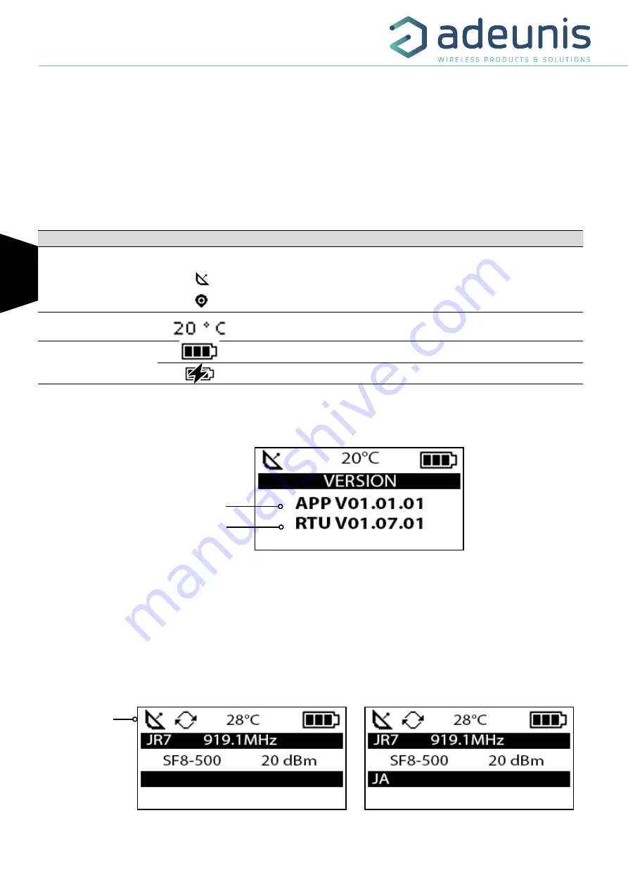
• The START screen (Showing the firmware version) - Only on the powering up
• The JOIN screen - Only on the powering up and after a command mode exit
• The UPLINK/DOWLINK screen
• The GPS screen
• The PER screen (Packet Error Rate)
• The DOWNLINK FRAME screen
The following icon are present on each screen of the product
Item
Icon
Description
GPS status
(First on the left)
No icon
GPS has been deactivated
GPS has not been synchronised
GPS has been synchronised
Temperature
(Third on the left)
Temperature in °C
Battery
(Last on the left)
Battery level
Product in charge
3.1. Start Screen
The device is switched on using the ON/OFF switch located on the underside of the device. Once it has been switched on, the device’s LCD screen
will light up and the start menu will be displayed. This screen show the 2 firmware versions during few seconds.
NOTE :
If the device does not switch on, this could mean that there is insufficient battery charge. You would then need to connect the device to
a USB charger. When the battery is completely empty, it is possible that the device will not switch on, even when connected. Please wait a few
minutes before the device can be used.
3.2. Join Screen
When the device is configure in OTAA mode (Over the Air Activiation) default mode, the product start a join request session (JRx) and show the
frequency, SF and power used during this sesssion. When the product receive a Join Accept (JA) from the network, the information is displayed
on the screen and the product switch to the main screen (Uplink/Downlink).
Applicatif Firmware Version
RTU Firmware version
Figure 5 : Firmware version
Status bar
Figure 6 : Join Request
Figure 7 : Join Accept


