background image


Adept Ltd, 2-6 McDonald Street, Morningside, Auckland 1025, New Zealand                                       

Page 

8 of 10 

www.adeptclip.com 

Important:  Ensure the Lower Arm 

(Part No 14)

 is installed on the bottom inserter 

mounting point. The Lower Arm is smaller than the Upper Arms and must be installed 

in the bottom position for correct F4 operation.


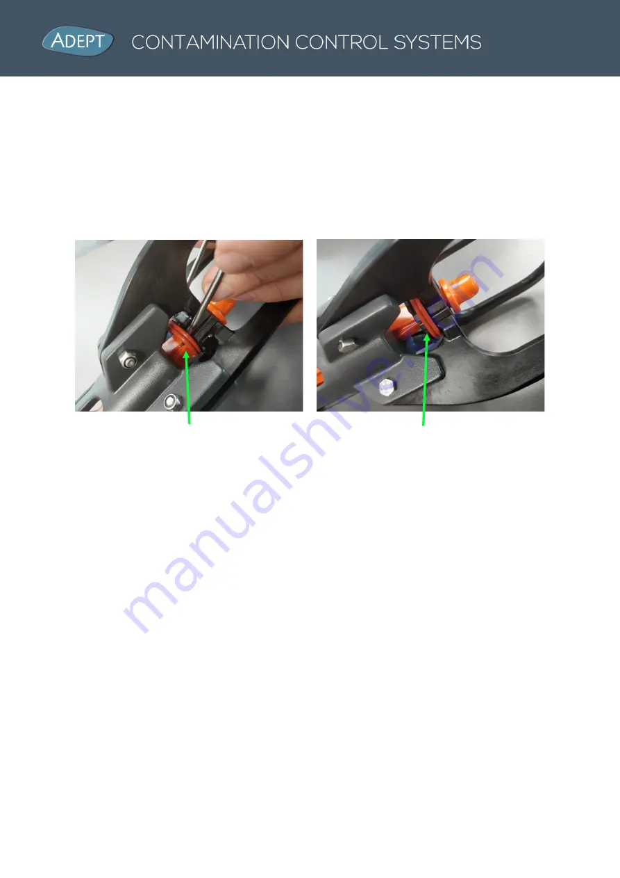
4.3  O-Ring installation


Remove the worn O Rings 

(Part No 25)

 from the hooks on the Lower 

(Part No 14) 

and 

Upper arms 

(Part No 15) 

using an O Ring removal tool or screwdriver to pry them off. 

Replace with 2 x new items. 


Pry off old worn O Rings                                      New O Rings installed on Arms


5.  Troubleshooting 


1.  F4 Inserter is inactive and will not activate: 


  Is unit connected to mains air source? 

  Is there a restriction in the hose? 

  Is there mechanical obstruction preventing the ram moving forwards? 

  Is there a mechanical obstruction preventing the trigger being pressed? 


2.  F4 Inserter is difficult to insert:


  Do all four arms return to meet centrally? 

  Is the pressure source set within operating range of 80 – 120 PSI? 

  Is there a mechanical obstruction preventing the ram to travel at full force? 

  Check if the actuating rod or arms are worn and require replacement. 


3.  F4 Inserter arms do not meet in the middle:  

  Have the O Rings broken or been misplaced? 

  Are the arms free to pivot or are they restricted by entrapped dirt? 

  Check for wear on the arms or the arm spacers. 


Summary of Contents for F4 INSERTER

Page 1: ...Adept Ltd 2 6 McDonald Street Morningside Auckland 1025 New Zealand Page 1 of 10 www adeptclip com F4 INSERTER INSTRUCTION AND SERVICE MANUAL www adeptclip com...

Page 2: ...1 3 Intended Use 3 1 4 Warnings 3 2 Installation 3 2 1 Compressed Air Connection 3 2 2 Suspending the F4 Inserter 4 3 Operation 5 3 1 Plug Loading 5 3 2 Plug Insertion 5 3 3 Cleaning 5 4 Maintenance K...

Page 3: ...mly forwards so they are recessed in to approximately 30mm Pull the trigger while holding the F4 inserter forward allowing the orange ram to extend to maximum travel Releasing the trigger will retract...

Page 4: ...nector is not suitable it may be changed to suit the coupling system available 2 2 Suspending the F4 Inserter The F4 Inserter is supplied with a spring hook carabiner on the top of it This is where yo...

Page 5: ...s for the anus and push firmly forwards so they are recessed in to approximately 30mm Pull the trigger while holding the F4 inserter forward allowing the orange ram to extend to maximum travel Maintai...

Page 6: ...nce kit comprises of Item Description Part No Qty A F4 Inserter Actuating Rod 1503 011E 1 B F4 Inserter Lower Arm Including new wear pad 1510 011 1 C F4 Inserter Upper Arm Including new wear pad 1510...

Page 7: ...tuating rod and reassemble the F4 4 2 Lower and Upper Arm replacement Use an 8mm Spanner to remove the 3 x Upper Part No 15 and 1 x Lower Arm Assemblies Part No 14 from the F4 Housing Install replacem...

Page 8: ...rms 5 Troubleshooting 1 F4 Inserter is inactive and will not activate Is unit connected to mains air source Is there a restriction in the hose Is there mechanical obstruction preventing the ram moving...

Page 9: ...Adept Ltd 2 6 McDonald Street Morningside Auckland 1025 New Zealand Page 9 of 10 www adeptclip com 6 Part Identification Diagram...

Page 10: ...t Straight 8mm to G1 4 F 1503 013 1 12 Air Connector Push Fit Straight 8mm to G1 8 F 1503 014 1 13 F4 Inserter Actuating Rod 1503 011E 1 14 F4 Inserter Lower Arm 1510 011 1 15 F4 Inserter Upper Arm 15...

Reviews: