background image


2. Charging Operation 

1.


  Plug the battery charger into the proper AC power source. The charging indicator light 
will flicker in green color and the charger operates in standby mode. 

2.


Insert the battery pack fully into the battery charger and the charger starts charging. 

The battery charger can detect some sort of failure caused by the battery and indicates by the 
statuses of the red and green indicator lights. 


When a failure occurs, remove the battery 
and then insert it into the charger again. If the 
failure continues, change with a new battery. 
If the new battery can be charged, then the 
old battery maybe damaged. If the charging 
indicator lights indicate same failure as 
before while changing with a new battery, 
then the charger maybe damaged, take the 
charger to be repaired by qualified 
serviceman. (Fig. 5) 


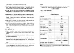
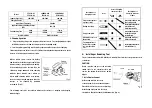
The following chart lists the relations between the statuses of charging and charging 
indicator lights. 

Descriptions of 

Charging Status 

Icons 

Icons of Charging 

Indicator Lights 

Descriptions of 

Charging Indicator 

Lights 

Green 

Light 

Red 

Light 

Plug the charger into 
a proper outlet 


Green light flickers, red 
light extinguished 

During charging 


Green light extinguished, 
red light keeps


flickering steadily 

Charge complete 


Green light keeps up   

steadily, red light 
extinguished 

Abnormity occurs on 
the battery 


Green and red light 
flicker alternately 

The temperature of 
the battery is under 
0

 or higher than 

50


Green light extinguished, 
red light flickers 


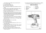
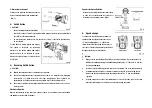
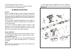
Installing or Removing Tool 

The tool here includes driver bit, drill bit, etc, which differs from the concept of power tools 
or machines. 

CAUTION: 

Before operation, always set  the  reversing 
switch lever  in the central position


and 

remove the battery. Mustn’t press switch 
trigger. 

1. Installing instrument 

Hold the ring and turn the sleeve 
counterclockwise to open the chuck jaws. 
Place the bit in the chuck as far as it will go. 
Hold the ring firmly and turn the sleeve 
clockwise to tighten the chuck (view backwards). (Fig. 6) 
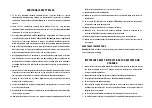
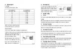
 

Model 

FFCL18-01 
FFCL18-03 

SCHARG-001 

FFCL18-04 

SCHARG-001 

(FFCL18-05) 

Input Voltage (AC) 

220-240V 

110-240V 

220-240 

Charging Current 

3.0A 

2.0A 

Input Power Frequency 

50-60Hz 

Applicable Battery Cartridge Voltage   

(DC) 

14.4-18V 

Full Charging Time 

2.0Ah 

≈45min   

≈70min 

4.0Ah 

≈90min 

≈135min 

Insulation Grade 

Double Insulation 

Summary of Contents for MAC AFRIC SDRILC-005

Page 1: ......

Page 2: ...ce RCD protected supply Use of an RCD reduces the risk of electric shock NOTE The term residual current device RCD may be replaced by the term ground fault circuit interrupter GFCI or earth leakage circuit breaker ELCB Personal Safety 10 Stay alert watch what you are doing and use common sense when operating a power tool Do not use a power tool while you are tired or under the influence of drugs a...

Page 3: ...r battery 25 Use power tools only with specifically designated batteries Use of any other batteries may create a risk of injury and fire 26 When battery is not in use keep it away from other metal objects like paper clips coins keys nails screws or other small metal objects that can make a connection from one terminal to another Shorting the battery terminals together may cause sparks burns or a f...

Page 4: ...ews 8 Secure the workpiece A workpiece clamped with clamping devices or in a vice is held more secure than by hand 9 Keep working area clean Blends of materials are particularly dangerous Dust from light alloys can burn or explode 10 Always wait until the tool has come to a complete stop before placing it down The drill bit insert can jam and lead to loss of control over the tool 11 Keep hands awa...

Page 5: ...essively shorter after charging stop operating immediately and replace with a new one or go to maintenance for inspection Continuous using of a worn out battery may result in a risk of overheating possible burns and even an explosion 16 Do not expose battery cartridge to rain snow or wet conditions 17 Store battery cartridge properly a Store the battery after it is fully charged b Store the batter...

Page 6: ... objects Fig 2 2 Removing the Battery To remove the battery press the unlocking buttons on both sides of the battery and pull out the battery downwards Fig 3 Battery Indicator CAUTION The four charging lights may flash in red color if the tool is overheated or overloaded As temperature recovers or over load protection is removed press the switch and the tool can be started normally Current power o...

Page 7: ...t Red Light Plug the charger into a proper outlet Green light flickers red light extinguished During charging Green lightextinguished red light keeps flickering steadily Charge complete Green light keeps up steadily red light extinguished Abnormity occurs on the battery Green and red light flicker alternately The temperature of the battery is under 0 or higher than 50 Green lightextinguished red l...

Page 8: ...s set to the center position Clockwise Rotation Depress the reversing switch lever from side B to side A for clockwise rotation for drilling and driving in screws view forwards Counterclockwise Rotation Depress the reversing switch lever from side A to side B for counterclockwise rotation for loosening or unscrewing screws Fig 9 Speed change To change the speed first switch off the tool and then s...

Page 9: ...e life of the tool There is a tremendous force exerted on the tool bit at the time of break through Hold the tool firmly and exert care when the bit begins to break through the work piece A stuck bit can be removed simply by setting the reversing switch to reverse rotation in order to back out However the tool may back out abruptly if you do not hold it firmly Always secure small workpieces in a v...

Page 10: ...s to be screwed in even when the battery runs out and allows the tool to be used as hand tool Over load Protection The motor will stop running when it is overloaded To restart the tool release the switch trigger first to reset the switch and then switch on the machine Overheated Protection When using as intended for the tool cannot be subject to overload When the load is too high or the allowable ...

Page 11: ...tained by maintenance companies recognized by original manufacturer The end users and maintenance departments are not allowed to change original parameter of the tool or adopt alternate materials whose performance is lower than original ones or spare parts that don not correspond to the specifications Cleaning Ventilation Slots For safe and proper working always keep the power tool and its ventila...

Page 12: ...695ZZ R 1350ZZ 7 Armature Assembly 8 Ball Bearing 625ZZ 9 Stator Assembly 10 Brush Holder Assembly 11 Spring Left 12 Spring Right 13 Carbon Brush 14 Rear Cover 15 Pan Head Tapping Screw ST2 9 20 16 Auxiliary Handle Assembly 17 Left half Motor Housing 18 Buckle 19 Pan Head Screw M4 10 20 Lock Nut M4 21 Pan Head Tapping Screw ST2 9 16 22 Shade 23 Right half Motor Housing 24 Nameplate 25 Reversing Sw...

Page 13: ...aring 699ZZ 9 Washer 33 46 3 6 34 Rotation Cam 10 Clutch Spring 35 Fixing Bushing 11 Washer 16 5 19 4 0 4 36 Hammer Spring 12 Adjusting Nut 37 Hammer Change Base 13 Ball Bearing 6900ZZ 39 Pan Head Tapping Screw ST2 9 13 14 Hemmer Change Plate 40 Speed Change Level 15 Torque Presetting Ring 41 Pan Head Tapping Screw ST2 2 16 Steel Ballφ2 38 42 Roller 3 53 17 Washer 10 1 15 2 0 5 43 Lock Plate 18 Dr...

Reviews: