background image

INST

ALLA

TION

5

CONFIGURA

TION

OPERA

TION

FUR

THER

INFORMA

TION

INDEX

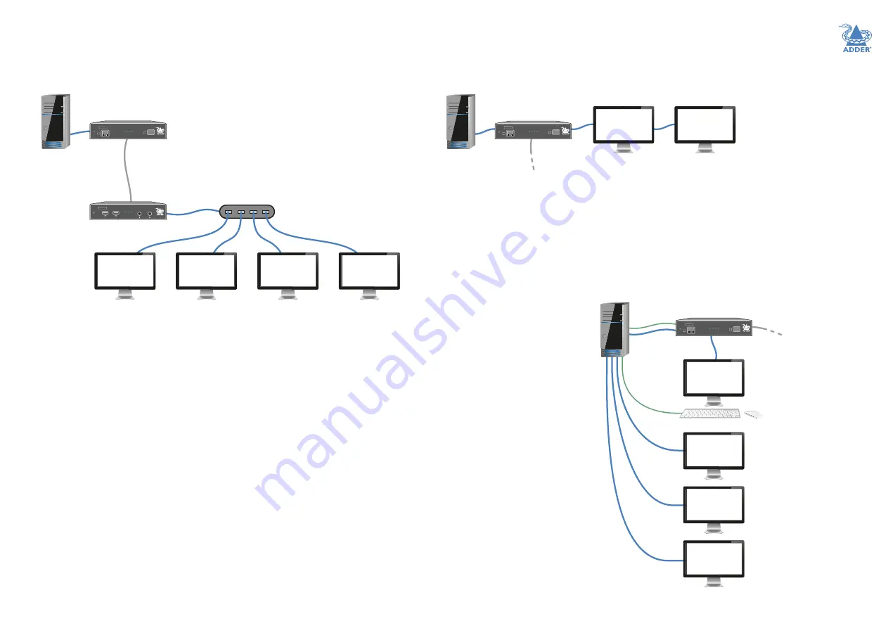
Multiple displays at the local console

ADDERLink XD612: 

You can optionally connect up to two video displays to the 

second video port of the transmitter to view the output locally: 

DP

link

DP

link

DP

link

1920 x 1200

@ 60 fps

ADDERLink

XD

6 1 2

PWR

LINK

LINK

A

B

STS VID LNK

T X

TRANSMIT

XD612

TX

1920 x 1200

@ 60 fps

Support for multiple non-MST video displays on XD614 (cont.)

An external MST hub can receive the combined DisplayPort MST signal from the first 

video port on the receiver and split out separate links to standard video displays (the 
second video output port on the receiver will be disabled): 

Adder does not supply MST hubs, but can recommend the following models:

•  Startech™ MST Hub 1x4 (MSTDP124DP)
•  Gofanco™ Prophecy MST hub 1x4 (PRO-MSTDP4DP)

XD614

RX

1920 x 1200

@ 60 fps

1920 x 1200

@ 60 fps

1920 x 1200

@ 60 fps

1920 x 1200

@ 60 fps

DP

link

DP

links

MST hub

Fiber

or

CATx

DP

link

ADDERLink

XD

6 1 4

PWR STS VID LNK

R X

R E C E I V E

ADDERLink

XD

6 1 4

PWR

LINK

LINK

A

B

STS VID LNK

T X

TRANSMIT

XD614

TX

You have several connection options:
• 

For a two display arrangement, connect an MST-compliant video display with another 

display (MST-compliant or not) in a daisy-chain arrangement.  

• 

If using two non MST-compliant video displays, connect one to the TX video output 
port and the other directly to the host computer’s video adapter, similar to the upper 

part of the example shown below. 

• 

If only a single local display is required, a non-MST display can be connected directly to 

the video output port.

On both types of transmitters, 
there are no console USB outlets, 

so if a local keyboard and/or 

mouse are required, they need to 

be connected directly to the host 
computer.

DP link

DP link

DP

link

DP

link

DP

link

USB link

USB

link

Stream

1

Stream

2

Stream

3

Stream

4

ADDERLink

XD

6 1 4

PWR

LINK

LINK

A

B

STS VID LNK

T X

TRANSMIT

XD614

TX

Fiber or

CATx

to RX

ADDERLink XD614

 supports 

just one console video display 
at the transmitter. If other 
local console video displays are 

required, then streams 2 to 4 can 

be accessed directly from the host 
computer’s video adapter.

Note: The display connected to the 

local console should support at 

least equal video resolution of that 

connected at the RX, otherwise no 

video will be displayed.

Summary of Contents for ADDERLink XD612

Page 1: ...ADDERLink XD612 and XD614 User Guide Experts in Connectivity Solutions Extender Solutions ...

Page 2: ...ansmitter audio links 12 Transmitter USB links 13 Transmitter Remote port 13 Transmitter power connection 14 Linking 15 CATx link 15 Fiber optic link 16 Receiver video display s 17 EDID management 17 Receiver audio devices 17 Receiver USB devices 18 Receiver Remote port 18 Receiver power connection 19 Configuration Accessing the Dashboard 20 Choosing RX video mode XD614 models only 20 Resetting a ...

Page 3: ...us two other USB devices up to USB 2 0 An RS232 serial device at speeds up to 115200 baud Mono microphone Stereo speakers digital stereo audio out Line level audio in out connections Transmission distances when using fiber The choice of fiber used with the ADDERLink XD modules has a considerable effect on the distance over which operation can take place Using multi mode fiber you can achieve dista...

Page 4: ...he quality of the cable terminations CAT6 is recommended for CATx extensions with a gauge thickness of at least 23AWG Up to 5Gb s of data may be transmitted so the cable must be rated for at least 5GBase T or 250MHz Patch links affect performance For each additional break patch within a run the overall maximum extension is likely to be reduced The amount will be dependent upon the nature of the pa...

Page 5: ... they can use the first and second video streams respectively See page 20 You can optionally use an external MST hub which will receive the combined DisplayPort signal from the first video port on the receiver and split out separate links to the standard video displays see next page Notes When using more than one video display the host s video adapter operating system and applications must support...

Page 6: ... LNK T X TRANSMIT XD614 TX You have several connection options For a two display arrangement connect an MST compliant video display with another display MST compliant or not in a daisy chain arrangement If using two non MST compliant video displays connect one to the TX video output port and the other directly to the host computer s video adapter similar to the upper part of the example shown belo...

Page 7: ...ard mouse and other HID peripherals See Receiver USB devices for further details Status indicators These provide visual confirmation of various system functions See Indicators for further details Power input See Receiver power connection for further details Audio ports Connect your microphone and headphones See Receiver audio devices for further details Receiver module SFP slot Accommodates a fibe...

Page 8: ...eiver USB devices for further details Status indicators These provide visual confirmation of various system functions See Indicators for further details Power input See Receiver power connection for further details Remote port Can be used for RS232 serial devices See Receiver remote port for further details Audio ports Connect your microphone and headphones See Receiver audio devices for further d...

Page 9: ...Tx Rx 530k 520k hours MTBF Pair 260k hours Local unit Transmitter Tx 4 x tri color status indicators DisplayPort in and local pass through out 2 x USB2 0 type B Line in and out analog audio RJ12 serial port RJ45 and SFP ports Remote unit Receiver Rx 4 x tri color status indicators 2 x DisplayPort out 4 x USB2 0 type A Mic in headset and speaker out RJ12 serial port RJ45 and SFP ports Physical desi...

Page 10: ...INK A B STS VID LN K T X TRANSM IT ADDERLink XD61x transmitter module Power adapter with locking connector and country specific power cord Audio cable 3m 3 5mm stereo jacks USB cable 2m type A to B DisplayPort cable 2m ADDERLink XD61x receiver module XD61x transmitter kit XD61x receiver kit Information wallet containing Quick setup guide Eight self adhesive rubber feet Safety document Power adapte...

Page 11: ... specific power cords CAB IEC AUS Australia CAB IEC EURO Central Europe CAB IEC UK United Kingdom CAB IEC USA United States CAB IEC JAPAN Japan Remote port serial cable 44cm Part number VSC50 DisplayPort cables 2m Part numbers VSCD18 for use with XD612 or XD614 units VSCD17 for use with XD612 units only SFP module with LC connectors Multi mode SFP MM LC 10G Single mode SFP SM LC 10G Dual ADDERLink...

Page 12: ...hin the supplied safety leaflet Connections do not need to be carried out in the order given within this guide however where possible connect the power in as the final step CONNECTIONS Installation involves linking the transmitter module to various ports on the host computer while the receiver module is attached to your video display s and peripherals Click a connection to see details Suitable for...

Page 13: ...ort various resolutions see the box below To connect the video port s 1 Connect the supplied DisplayPort link cable between the video socket 1 on the transmitter module rear panel and the video output socket of the host computer 2 Optionally connect local video display s to video socket 2 on the transmitter module rear panel See page 4 RECEIVER LINK POWER IN VIDEO LINK S USB LINK S AUDIO LINKS TRA...

Page 14: ...ppendix 1 for pin out details of the Remote port From the serial port of your host computer Transmitter USB links The transmitter module has two USB input ports on its rear panel USB links from the host computer RECEIVER LINK POWER IN VIDEO LINK S USB LINK S AUDIO LINKS TRANSMITTER REMOTE PORT REMOTE RECEIVER LINK POWER IN VIDEO LINK S USB LINK S AUDIO LINKS TRANSMITTER REMOTE PORT R REMOTE 2 1 Th...

Page 15: ...sp the outer body of the power adapter plug where it connects with the module 3 Gently pull the body of the outer plug away from the module As the body of the plug slides back it will release from the socket and you can fully withdraw the whole plug IMPORTANT Please read and adhere to the electrical safety information given within the supplied safety leaflet In particular do not use an unearthed p...

Page 16: ...eiver rear panel ADDERLink XD 6 1 2 LINK A LINK A Transmitter front panel Receiver rear panel Linking ADDERLink XD transmitters and receivers can be linked using either CATx see below or Fiber see next page CATx status indicators The status indicators on the CATx port connector of each module provide further status information when a CATx link is in use SPEED This indicator signals whether the spe...

Page 17: ...ors 5 Insert the fiber optic connectors into the SFP module so that they click into place 6 Repeat steps 4 and 5 at the other end LINK B T X TRANSMIT DC LINK B Transmitter front panel Receiver rear panel To remove an SFP module 1 If fitted remove the dual fiber optic connectors from the SFP module press in the release tab of the fiber optic connectors to disengage them 2 Unclip the small extractio...

Page 18: ...ionally use the rear panel 3 5mm jack audio socket to connect line level audio devices such as powered speakers VID LNK R X RECEIVE To stereo headphones From mono microphone To speakers TRANSMITTER LINK VIDEO DISPLAY S USB DEVICES AUDIO DEVICES POWER IN REMOTE PORT RECEIVER 2 TRANSMITTER LINK VIDEO DISPLAY S USB DEVICES AUDIO DEVICES POWER IN REMOTE PORT RECEIVER To primary video display or the fi...

Page 19: ...Create an RS232 serial connection with the receiver module When serial devices are attached to the Remote ports on the transmitter and receiver modules the units transparently convey the signals between them at rates up to 115200 baud no serial configuration is required An optional serial cable part number VSC50 is available from Adder To connect the Remote port 1 Use the optional serial cable VSC...

Page 20: ...disconnect the power adapter 1 Isolate the power adapter from the mains supply 2 Grasp the outer body of the power adapter plug where it connects with the module 3 Gently pull the body of the outer plug away from the module As the body of the plug slides back it will release from the socket and you can fully withdraw the whole plug IMPORTANT Please read and adhere to the electrical safety informat...

Page 21: ...Link XD receivers contain an internal DisplayPort MST hub On the XD614 models you can choose to either use it or bypass it When bypassed default setting the full combined MST Multi Stream Transport signal received from the transmitter is sent directly to video port 1 If the internal hub is engaged then the first and second SST video streams Single Stream Transport are decoded and sent to ports 1 a...

Page 22: ...ent such as a straightened paperclip in the reset hole until the receiver s STS indicator flashes red blue The receiver is now in upgrade mode 4 Wait for the STS indicator link to turn green signifying that the link is established 5 Insert the memory stick containing the upgrade file into the front panel left USB port The upgrade should begin and both units will flash their STS indicators red gree...

Page 23: ...his indicator shows the status of the link between the transmitter and receiver modules Off no link Red 0 25 quality Amber 25 50 quality Yellow 50 75 quality Green 75 100 quality CATx status indicators The status indicators on the CATx port connector of each module provide further status information when a CATx link is in use SPEED This indicator signals whether the speed of the CATx link is suffi...

Page 24: ...rmation including the following Getting assistance see right Appendix 1 Remote Options port pin out GETTING ASSISTANCE If you are still experiencing problems after checking the information contained within this guide then please refer to the Support section of our website www adder com Further information ...

Page 25: ...pin out is listed below Note Although the pins labeled Not used is inactive it is still connected internally and so no links should be made at all to this pin Pin Signal 1 Sense 5V 2 Not used 3 Not used 4 GND 5 RX 6 TX Note TheTX detects presence of an incoming power signal to determine whether 5V should be supplied at the RX 1 6 REMOTE ...

Page 26: ...25 INSTALLATION CONFIGURATION OPERATION FURTHER INFORMATION INDEX www ctxd com Documentation by 2021 Adder Technology Limited All trademarks are acknowledged Part No MAN 000014 Release 1 4 www adder com ...

Page 27: ...pgrade 21 H HID 13 L Linking overview 15 M MST 4 20 Multi Stream Transport 20 O Optional extras 10 OSD Dashboard 20 P Power connection Receiver 19 transmitter 14 R Remote port pin out 24 Receiver 18 transmitter 13 Reset 21 S SFP modules 2 16 Single Stream Transport 20 SST 20 Status indicators 22 Supplied items 9 U Upgrade firmware 21 USB devices Receiver 18 USB links transmitter 13 V Video display...

Reviews: