ADDAC SYSTEM
page 6
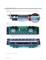
STEP 6:
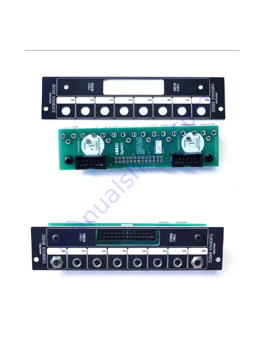
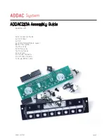
Locate the right panel and proceed by placing it.
ADDAC213A Assembly Guide
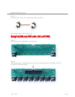
STEP 7:
Tighten both top screws and jack nuts.
Page 1: ......
Page 2: ...DDAC SYSTEM page 2 Parts included in the kit 2x Front Panel 2x Pcb 4x 10mm female female spacer 8x M3 fiber washer 12x M3 screws 4x Nutted Jacks 12x No nut Jacks 4x Jack nuts 4x 2x5 IDC Connector 2x 2...
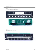
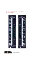
Page 3: ...de ADDAC SYSTEM page 3 STEP 1 Locate Pcb and panels The Kit contains the 213A modules pair Left and Right module Here s how you can identify which is which LEFT PAIR RIGHT PAIR JACKS ORIENTATION JACKS...
Page 4: ...you can follow the same principles to assemble the Left module STEP 1 Locate pcb and place the 2x5 IDC boxed headers notice the orientation of the headers below After placing proceed to solder it s p...
Page 5: ...ader once again notice the orientation of the header below STEP 4 Next we ll place the threaded jacks on both ends We ll now populate all front panel parts DO NOT SOLDER ANY PART UNTIL THE LAST STEP S...
Page 6: ...ADDAC SYSTEM page 6 STEP 6 Locate the right panel and proceed by placing it ADDAC213A Assembly Guide STEP 7 Tighten both top screws and jack nuts...
Page 7: ...re all done ADDAC SYSTEM page 7 STEP 8 We ll now start soldering first solder 1 pin of the 2x13 IDC try soldering it as raised as possible like shown below STEP 8 Finally solder all other pads ADDAC2...
Page 8: ...ADDAC213A ASSEMBLY GUIDE For feedback comments or problems please contact us at addac addacsystem com November 2017 Revision 01...