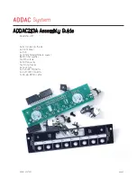
ADDAC213A Assembly Guide
ADDAC SYSTEM
page 4
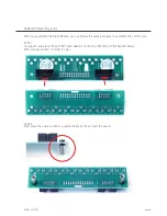
We’ll now assemble the Right Module, you can follow the same principles to assemble the Left module.
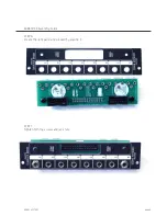
STEP 1:
Locate pcb and place the 2x5 IDC boxed headers, notice the orientation of the headers below.
After placing proceed to solder it’s pins.
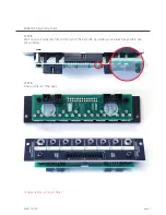
STEP 2:
Next place the spacers adding a washer between the pcb and the spacer.
Summary of Contents for ADDAC213A
Page 1: ......


