background image

SCP-PLL735-010-03H 

56

January 6, 2003

 PLL-735 Lists 1, 2 and 3

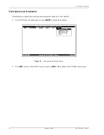
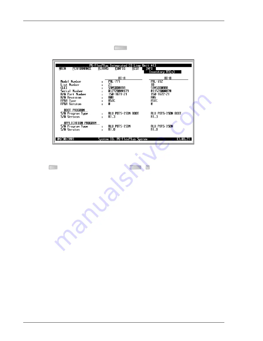
RTs Inventory Screen

This screen displays all pertinent information about the connected RTs.

1

Select the 

Inventory RT(s) 

option and press 

 to display the screen:

Figure 48. 

Inventory RT(s) Screen

2

Press 

 to return to the DICOLU main screen, or 

 +   to return to the PAU/PMU main menu.

ENTER

ESC

CTRL

R

Summary of Contents for PG-FLEXPLUS PLL-735

Page 1: ...PG FLEXPLUS TECHNICAL PRACTICE SECTION SCP PLL735 010 03H Model List CLEI Code PLL 735 1 S9L1AR0A PLL 735 2 S9L1AREA PLL 735 3 S9L1ARFB ...

Page 2: ...tems Inc and shall not be modified used copied reproduced or disclosed in whole or in part without the written consent of ADC Contents herein are current as of the date of publication ADC reserves the right to change specifications at any time without notice Information furnished by ADC is believed to be accurate and reliable In no event shall ADC be liable for any damages resulting from the loss ...

Page 3: ...pment is short or irregular contact ADC as described in Returns on page 63 If you must store the equipment for a prolonged period store the equipment in its original container Notes indicate information about special circumstances Cautions indicate the possibility of equipment damage or the possibility of personal injury Electrostatic Discharge ESD susceptibility symbols indicate that a device or ...

Page 4: ...Inspecting Your Shipment SCP PLL735 010 03H January 6 2003 PLL 735 Lists 1 2 and 3 ...

Page 5: ...____________________ 8 Required Tools and Test Equipment 8 Installing the DICOLU 8 Initialization Sequence 9 Subscriber Drop Tests 9 Administration ______________________________________________________________________ 10 Front Panel Craft Port to Terminal Connections 10 Front Panel Craft Port to Modem Connections 11 Backplane Craft Port to Terminal Connections 11 Backplane Craft Port to Modem Con...

Page 6: ...reens 45 Set Factory Defaults Screen 48 Test Submenu 49 HDSL A and HDSL B SDT Screen for POTS RTs 50 HDSL A and HDSL B SDT Screen for ISDN RTs 52 Information Submenu 54 Inventory COLU Screen 55 RTs Inventory Screen 56 COLU Event Log Screen 57 RT Event Logs Screen 58 Help Screen 59 Fault Isolation _______________________________________________________________________ 60 DICOLU and RT Fault Indicat...

Page 7: ...enu 18 14 DICOLU Menu Structure 19 15 Main Submenu 20 16 Overall Status Screen 21 17 HDSL A Status Screen 22 18 Performance Submenu 24 19 HDSL A Summary Screen 25 20 HDSL A 24 Hr History Screen 26 21 HDSL A 24 Hr History Page History Forward Screen 26 22 HDSL A 7 Day History Screen 28 23 IDSN1 B Summary Screen 29 24 ISDN B 7 Hr History Screen 30 25 Alarms Submenu 31 26 System History Screen 32 27 ...

Page 8: ... A Subscriber Drop Test Screen 50 42 POTS1 HDSL A Subscriber Drop Test Results Screen 51 43 HDSL B Subscriber Drop Test Screen with IDSN1 Selected 52 44 ISDN1 HDSL B Subscriber Drop Test Screen with a Warning Message Displayed 52 45 IDSN1 HDSL B Subscriber Drop Test Results Screen 53 46 Information Submenu Screen 54 47 Inventory COLU Screen 55 48 Inventory RT s Screen 56 49 COLU Event Log Screen 5...

Page 9: ...3 3 LED Descriptions 7 4 Subscriber Drop Test Components 9 5 Craft Port Configuration 12 6 Overall Status 21 7 Channel Status 23 8 System Options Configuration Fields 36 9 System Alarm Types 37 10 HDSL Alarm Threshold Fields 38 11 Alarm Reports 39 12 HDSL Alarms 40 13 ISDN A B Options Fields 42 14 ISDN A B Alarm Threshold Fields 44 ...

Page 10: ...SCP PLL735 010 03H vi January 6 2003 PLL 735 Lists 1 2 and 3 ...

Page 11: ...Subscriber Line HDSL technology Using existing cable PG FlexPlus provides for higher bandwidth needs of residential and business customers by providing multiple subscriber services on a single twisted pair wire Each DICOLU is installed in the COTS and interfaces with two corresponding RTs Digital lines from the Central Office CO connect to the COTS and are sent by means of the DICOLU and the HDSL ...

Page 12: ...5 to 95 noncondensing Altitude 200 ft to 13 000 ft 60 m to 4 000 m Compliance NEBS SR 3580 for Level 3 ESD Per GR 1089 CORE Power and Lightning Per GR 1089 CORE Human Safety UL 1950 for Restricted Access Emissions Radiation and Immunity Per GR 1089 CORE for Class A equipment Dimensions Height 5 50 in 14 0 cm Width 1 10 in 2 8 cm Depth 10 25 in 26 0 cm Weight 1 00 lbs 0 5 kg Table 1 HDSL Lines DS0s...

Page 13: ...is the total power that the DICOLU consumes or draws from the CO battery This parameter is needed when the DICOLU is located remotely from its serving CO It determines the battery capacity required to maintain an 8 hour standby battery reserve for emergency situations Maximum Current Drain The maximum current drain is the maximum current drawn from the CO battery supply when it is at its minimum v...

Page 14: ...ve UAS performance parameter You can set the severity of the alarm at the HDSL A and HDSL B Alarm Types Screens on page 39 View the results of these settings at the HDSL A and HDSL B Summary Screens on page 25 HDSL ES An interval of 1 second during which at least one CRC is detected at the incoming HDSL port You can set the value of this parameter for the DICOLU and the RT at the HDSL A and HDSL B...

Page 15: ...l circuits are placed in a Trunk Conditioned state BKUPMEMP EEPROM Failure NORTSWn RTn has no application software and is awaiting software download Alarm Types Any alarm may be set the alarm to any of these values Major MJ Minor MN Critical CR Not Alarmed NA Not Reported NR History Current cumulative counts of the past 24 hours and historical data in the form of a 24 hour history in 15 minute inc...

Page 16: ... suppressed when initially installed and powered up Any alarms that are generated during this process are suppressed When the HDSL circuit is synchronized and the DICOLU and RT margin has cleared outstanding alarms that have been suppressed are made active and reported to the PAU or the PMU based upon their provisioned types Table 3 describes the LEDs on the DICOLU front panel If you have installe...

Page 17: ...sync between the PLL 735 and RT Flashing HDSL is not in sync between the PLL 735 and RT Off PLL 735 is not receiving CO battery SYNC Green On HDSL is in sync between the PLL 735 and RT Flashing HDSL is attempting to sync between the PLL 735 and RT Off No RT is detected MARGI N Yellow On PLL 735 HDSL margin is below the preset threshold Flashing RT HDSL margin is below the preset threshold Off PLL ...

Page 18: ...treat the HDSL pair as if it were live with high voltage present Use caution when installing an HDSL pair that is already connected to a DICOLU because dangerous voltages are present on the HDSL pair The DICOLU unless previously disabled by means of craft provisioning periodically attempts to power up the RT by applying 100 Vdc with respect to ground to the HDSL pair The DICOLU also initiates a st...

Page 19: ...ynchronize every 5 minutes until synchronization is achieved MARGIN LED is on yellow indicating the DICOLU signal to noise ratio is equal to or below the selected signal to noise ratio threshold on the DICOLU The MARGIN LED Flashes if the signal to noise ratio of the HDSL line is equal to or below the selected signal to noise ratio threshold on the RT SUBSCRIBER DROP TESTS Select the Subscriber Dr...

Page 20: ...e allows real time updating of information displayed on the screen rather than requiring technician interaction to refresh the screen Through the craft interface screens system administration functions such as alarm checking and clearing configuration changes and performance monitoring and testing can be performed FRONT PANEL CRAFT PORT TO TERMINAL CONNECTIONS Connections between the RS232 craft p...

Page 21: ... or PAU drops Data Set Ready DSR and the unit will log off when the modem drops CD The following connections are required to make the modem work correctly see Figure 4 Front Panel Craft Port to Modem Connections on page 11 Figure 4 Front Panel Craft Port to Modem Connections BACKPLANE CRAFT PORT TO TERMINAL CONNECTIONS Use a null modem cable to connect to a DTE device from the backplane connector ...

Page 22: ...ane connector and a DCE DB 25 connector Figure 6 Backplane Craft Port to Modem Connections Refer to Table 5 Craft Port Configuration on page 12 to set up the VT 100 craft port connections Table 5 Craft Port Configuration Control Setting Supported Default Software Flow Control XON XOFF Enabled Enabled Baud Rate PAU 1200 2400 4800 9600 38400 PMU 1200 2400 4800 9600 14400 19200 28800 38400 57600 Auto...

Page 23: ...field options Moves up a menu level From the Main menu the Logout screen is displayed Returns to Main menu without accepting changes Returns to the main menu The banner briefly appears and then the main menu bar displays keys Selects an underlined or highlighted menu item A screen entry is made The factory default password is password 1 If you establish a different password you must type the new p...

Page 24: ...icable TL1 command reference practice for this information You can download this document from the ADC Technical Manuals web page at www adc com 3 When the terminal mode is both you can start a screens session by entering the following TL1 command chg dialog The TL1 parser returns with the following TL1 command response Figure 8 TL1 Command Response Screen Entering the TL1 prompt chg mode screens ...

Page 25: ...03 15 Figure 9 Login Password Screen 4 Type the password then press If an invalid password was entered the Login screen will be re displayed with the message Invalid Password Try Again 5 The banner displays briefly then the PMU main menu is displayed ENTER ...

Page 26: ...p If you do not know the slot number a Select the menu option MAIN at the PMU main screen and press to view the submenu b Select the submenu option Shelf Summary and press to display the inventory of the shelf COLUs Note the slot number then press to return to the PMU main menu Continue with step 5 7 Move to the Select menu option and press to view the shelf slot list ENTER ENTER ESC ENTER ...

Page 27: ...ING OFF If you must leave your VT 100 terminal unattended log out until you are ready to resume work This prevents unauthorized persons from inadvertently changing any of the system operating parameters Log out by choosing Logout from the PMU main submenu bar or by disconnecting the cable connecting the terminal to the PMU 712 or COT shelf backplane connector ENTER ...

Page 28: ...s and Figure 14 DICOLU Menu Structure on page 19 is an illustrative map of DICOLU menu structure The date and times displayed are the default values for the system To set the date and time for the shelf at the PMU or PAU select the CONFIG submenu item Date and Time and press All COLUs in the shelf will update to the set date and time Figure 13 DICOLU Main Menu ENTER Current Date Current Time Provi...

Page 29: ...A History HDSL B History ISDN1 A History System Options System Alarm Types HDSL A Alarm Thresholds HDSL A Alarm Types HDSL B Alarm Thresholds HDSL B Alarm Types ISDN A Options IDSN A Alarm Thresholds ISDN A Alarm Types IDSN B Options ISDN B Alarm Thresholds ISDN B Alarm Types Set Factory Defaults Inventory RT s COLU Event Log RT Event Log Help Inventory HDSL B Subscriber Drop Test HDSL A Subscribe...

Page 30: ...the individual unit status 1 Select MAIN and press to view the submenu Figure 15 Main Submenu 2 Press to return to the DICOLU main menu or CTRL to return to the PAU PMU main menu Some screens illustrated in this document may be slightly different than what may appear on the craft interface terminal These adjustments are related to individual software installations ENTER ESC R ...

Page 31: ...Down HDSL link is down and System is not in Metallic Fallback Start up System in start up mode where the HDSL link is acquiring synchronization Normal System running normal where the HDSL link is synchronized and speech and signaling data are flowing between the DICOLU and the RTs Performance HDSL A Margin dB Summary of the A Margin in dB values HDSL A ES 24 Hr Summary of Errored Seconds occurring...

Page 32: ...t Table 7 Channel Status on page 23 describes the conditions that appear in the HDSL A Status and HDSL B Status screens 1 Select the HDSL A Status option or HDSL B Status option and press to view the screen Figure 17 HDSL A Status Screen ENTER Status indicators for the POTS interfaces the HDSL span and HDSL performance summary in terms of margin and ES count Status of current HDSL and System alarm...

Page 33: ...y detected and line is on hook at RT BUSY Line is off hook at RT RINGING Line is ringing TEST Testing is being done on line OPEN No CO battery detected FALLBACK HDSL circuit has reverted to POTS service for line 1 NOT PROVISIONED No active PMX is installed TRUNK CONDITION Forced line condition IDLE CO battery detected line is on hook at RT and the line is in ground start mode BUSY Line is off hook...

Page 34: ... to the DICOLU history and performance summary screens The DICOLU List 2 and List 3 support ISDN functions and would appear in this submenu 1 Select PERFORMANCE and press to display the submenu Figure 18 Performance Submenu 2 Press to return to the DICOLU main screen or to return to the PAU PMU main menu ENTER ESC CTRL R ...
Page 35: ...e data for the HDSL B connection in this same format 1 Select the HDSL A Summary option or HDSL B Summary option and press to view the screen The date and time of the last reset of the margin values for the selected RT display at the bottom of the screen Figure 19 HDSL A Summary Screen 2 Type at the Reset MIN MAX Margin Counts Y prompt to reset the counts The date and time of the last reset displa...

Page 36: ...same format 1 Select the HDSL A 24 hr History option or HDSL B 24 Hr History option and press to view the screen Figure 20 HDSL A 24 Hr History Screen If you have just installed this card and use the Page History Forward button an error message flashes at the bottom of the screen Figure 21 HDSL A 24 Hr History Page History Forward Screen The current 15 minute interval information shows the real ti...

Page 37: ...tervals 3 Select the Clear History button and press to clear the history The date and time of the last clearance of the history displays at the bottom of the screen 4 Press to return to the DICOLU main menu or to return to the PAU PMU main menu If there are active alarms associated with the current 24 hour performance history information those alarms become inactive when the 24 hour performance hi...

Page 38: ...U and RT ES and UAS performance parameters which have the valid field values of Unavailable The system has not run long enough to fill this register Partial Data is being collected for this register Complete Data is saved in the history register for the complete interval Adjusted The time or date has been changed on the system during the interval 2 Select a paging button and press to scroll throug...

Page 39: ...on and press to view the screen The date and time of the last reset of the IDSN counts display at the bottom of the screen Figure 23 IDSN1 B Summary Screen The DICOLU derives the hourly ES SES BE performance and the daily ES and SES performance parameters for both the DICOLU and the selected RT 2 Type at the CLEAR ISDN1 CURRENT COUNTS Y prompt to clear the counts The date and time of the last clea...

Page 40: ...The ISDN1 A screen displays in this same format the data for the ISDN1 A connection 1 Select the ISDN1 A 7 Hr History option or ISDN1 B 7 Hr History option and press to view the screen Figure 24 ISDN B 7 Hr History Screen The DICOLU derives the ES performance parameters for the DICOLU and RT 2 Press to return to the DICOLU main screen or to return to the PAU PMU main menu PLL 735 List 1 does not s...

Page 41: ...s HDSL POTS ISDN and system related alarmed events to the PAU or PMU 1 Select ALARMS from the main menu and press to display the submenu Figure 25 Alarms Submenu 2 Press to return to the DICOLU main screen or to return to the PAU PMU main menu PLL 735 List 1 does not support ISDN services ENTER ESC CTRL R ...
Page 42: ... System History option and press to view the screen Figure 26 System History Screen If no alarms are not present the word OK displays The date and time of the last clearance of the history displays at the bottom of the screen The current information shows real time updates 2 If you want to clear the history type at the Clear System Alarm History Y prompt 3 Press to return to the DICOLU main screen...

Page 43: ... Types Screens on page 39 The HDSL B screen displays the data for the HDSL B connection in this same format 1 Select the HDSL A History option or HDSL B History option and press to view the screen Figure 27 HDSL A History Screen If no alarms are present the word OK displays 2 Type at the Clear HDSL Alarm History Y prompt to clear the information 3 Press to return to the DICOLU main screen or to re...

Page 44: ...he ISDN1 A connection in this same format 1 Select the ISDN1 A History option or ISDN1 B History option and press to view the screen Figure 28 ISDN1 B History Screen If no alarms are present the word OK displays 2 Type at the CLEAR ISDN ALARM HISTORY Y prompt to clear the information 3 Press to return to the DICOLU main screen or to return to the PAU PMU main menu Clearing the alarm history clears...

Page 45: ...ystem provisioning options are saved in nonvolatile memory 1 Select CONFIG from the main menu and press to display the submenu Figure 29 Configuration Submenu Screen 2 Press to return to the DICOLU main screen or to return to the PAU PMU main menu PLL 735 List 1 does not support ISDN services The defaults for Lists 1 and 2 are different from List 3 although functionally identical ENTER ESC CTRL R ...
Page 46: ...rn to the PAU PMU main menu Table 8 System Options Configuration Fields Options Description List 1 and 2 Defaults List 3 Default POTS Ringing Frequency The ringing frequency sent from the RT to the subscriber Possible values include 20 Hz 25 Hz 30 Hz and 50 Hz 20 Hz 20 Hz HDSL A Periodic Power Up When Enabled the system periodically attempts to power up the RT Possible values are Enabled and Disab...

Page 47: ... System Alarm Types Changes button and press to accept the changes 4 Press to return to the DICOLU main screen or to return to the PAU PMU main menu Table 9 System Alarm Types Alarms Description List 1 and 2 Defaults List 3 Default MISMATCHA Incompatible RT A unit has been installed MN MN NORTSWA RT A has no application software and is awaiting software download MN MN MISMATCHB Incompatible RT B u...

Page 48: ... the next column Continue until you have made all desired changes 4 Move to the Accept HDSL Alarm Thresholds Changes button press to accept the changes 5 Press to return to the DICOLU main screen or to return to the PAU PMU main menu Table 10 HDSL Alarm Threshold Fields Thresholds Description List 1 and 2 Defaults List 3 Defaults MAR Value at which alarm is set active if margin drops equal to or l...

Page 49: ...L A Alarm Types option or HDSL B Alarm Types option and press to view the screen Figure 33 HDSL A Alarm Types Summary Screen 2 Select the desired field and press the to toggle to the desired value 3 Press a directional key to move up or down the current column or press to move to the next column Continue until you have made all desired changes 4 Move to the Accept HDSL Alarm Type Changes button an...

Page 50: ...ve if the count equals or exceeds the threshold in the current 24 hour interval MN NA UAS 15 MIN Active if the count equals or exceeds the threshold in the current 15 minute interval MN NA UAS 24 HR Active if the count equals or exceeds the threshold in the current 24 hour interval MN NA MAR Active if the margin equals or drops below the threshold MN NR PFO Open circuit detected on the HDSL span M...

Page 51: ...lts of these settings at the Overall Status Screen on page 21 The ISDN B screen displays the data for the ISDN B connection in this same format 1 Select the ISDN A Options or ISDN B Options line and press to view the screen Figure 34 ISDN A Options Screen 2 Select the desired field and press the to toggle to the desired value or use a directional key to move to the next option 3 Press to move to t...

Page 52: ...tly through to the RT with no interaction involved MP EOC SLAVE TRANSPARENT ISDN1 RT SES Count COLU RT Customer and Network SES An ISDN SES alarm is generated if the accumulated hourly SES count at the COLU RT reaches or exceeds this threshold value A single threshold value is used for thresholding errors in the customer or network direction The range of values is from 1 to 15 3 4 ISDN2 Sealing Cu...

Page 53: ...een displays the data for the ISDN B connection in this same format 1 Select the ISDN A Alarm Thrshlds option and press to view the screen Figure 35 ISDN A Alarm Thresholds Screen 2 With the desired field selected press the to toggle to the correct value for that field 3 Press a directional key to move up or down the current column or press to move to the next column Continue until you have made a...

Page 54: ...s include any number from 1 to 255 40 40 ISDN1 and ISDN2 RT Daily ES Threshold Value for the daily ES alarm Possible threshold values include any number from 1 to 4095 100 100 ISDN1 and ISDN2 RT Hourly SES Threshold Value for the hourly SES alarm Possible threshold values include any number from 1 to 127 10 10 ISDN1 and ISDN2 RT Daily SES Threshold Threshold value for the daily SES alarm Possible ...

Page 55: ... the results of these settings at the System History Screen on page 32 The ISDN B screen displays the data for the ISDN B connection in this same format 1 Select the ISDN A Alarm Types option or ISDN B Alarm Types option and press to view the screen Figure 36 ISDN A Alarm Types Screen 2 Select the desired field and press the to toggle to the desired value 3 Press a directional key to move up or do...

Page 56: ...faults List 3 Defaults Loss of Sync Word The ISDN link has lost synchronization NA NA Lost of Signal The ISDN link has lost the signal NA NA Customer Hourly ES The hourly ES count in the customer direction has exceeded this threshold NA NA Customer Daily ES The daily ES count in the customer direction has exceeded this threshold NA NA Customer Hourly SES The hourly SES count in the customer direct...

Page 57: ...t in the network direction has exceeded this threshold NA NA Data Transparency Lost The data transparency has been lost NA NA D Loss of Sync word The sync work on the D channel has been lost NA NA Table 15 ISDN A B Alarms Cont Types ISDN1 and ISDN2 Description List 1 and 2 Defaults List 3 Defaults ...

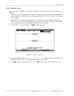
Page 58: ...iew the screen Figure 38 Set Factory Defaults Screen 2 Type in the field after the CONTINUE Y N prompt to reset the system to the Factory Default values or to maintain the current configuration defaults 3 Press to return to the DICOLU main screen or to return to the PAU PMU main menu The defaults for Lists 1 and 2 are different than List 3 although functionally identical ENTER Y N ESC CTRL R ...

Page 59: ...p by providing a test selection from the TEST menu The relays in the RT provide a path for performing a Subscriber Drop Test SDT 1 Select TEST from the main menu and press to display the submenu Figure 39 TEST Submenu Screen 2 Press to return to the DICOLU main screen or to return to the PAU PMU main menu ENTER ESC CTRL R ...

Page 60: ...orming a SDT 1 Select the HDSL A Subscriber Drop Test option and press to display the submenu Figure 40 HDSL A Subscriber Drop Test Selection Screen with POTS1 Selected 2 Select the POTS1 circuit to test and press to view the screen Figure 41 POTS1 HDSL A Subscriber Drop Test Screen PLL 735 List 1 does not support ISDN services ENTER ENTER ...

Page 61: ... continue or to cancel the test 3 If you typed to continue the test a message displays letting you know that a test is in progress 4 When the tests are completed the SDT results are displayed Figure 42 POTS1 HDSL A Subscriber Drop Test Results Screen 5 Press to return to the DICOLU main screen or to return to the PAU PMU main menu Y N Y ESC CTRL R ...

Page 62: ... or HDSL B Subscriber Drop Test option and press to display the submenu Figure 43 HDSL B Subscriber Drop Test Screen with IDSN1 Selected 2 Select the IDSN1 circuit to test and press A warning message displays explaining that calls in progress will be disrupted Type to continue or to cancel the test Figure 44 ISDN1 HDSL B Subscriber Drop Test Screen with a Warning Message Displayed PLL 735 List 1 d...

Page 63: ... When the tests are completed the results are displayed Figure 45 IDSN1 HDSL B Subscriber Drop Test Results Screen When the Network Termination portion of the test has a Status of Failed it indicates that no modem or other data device was there to complete the circuit 5 Press to return to the DICOLU main screen or to return to the PAU PMU main menu Y ESC CTRL R ...

Page 64: ...U The Information submenu provides technical information about the COLU and RTs 1 Select INFO from the main menu and press to display the submenu Figure 46 Information Submenu Screen 2 Press to return to the DICOLU main screen or to return to the PAU PMU main menu ENTER ESC CTRL R ...

Page 65: ... Screen The Inventory COLU displays all the critical information about the COLU 1 Select the Inventory COLU option and press to display the screen Figure 47 Inventory COLU Screen 2 Press to return to the DICOLU main screen or to return to the PAU PMU main menu ENTER ESC CTRL R ...

Page 66: ... Screen This screen displays all pertinent information about the connected RTs 1 Select the Inventory RT s option and press to display the screen Figure 48 Inventory RT s Screen 2 Press to return to the DICOLU main screen or to return to the PAU PMU main menu ENTER ESC CTRL R ...

Page 67: ...provisioning factory defaults were restored due to a corrupted database MEMCHK is informational only To clear the MEMCHK alarm go to the CONFIG submenu option Set Factory Defaults and Accept the Set Factory Defaults prompt No customer action is required 1 Select the COLU Event Log option and press to display the screen Figure 49 COLU Event Log Screen 2 Type in the field after the Clear Event Log H...

Page 68: ... The provisioning factory defaults were restored due to a corrupted database MEMCHK is informational only To clear the MEMCHK alarm go to the CONFIG submenu option Set Factory Defaults and Accept the Set Factory Defaults prompt No customer action is required 1 Select the RT Event Log option and press to display the screen Figure 50 RT Event Logs Screen 2 Type in the field after the Clear Event Log...

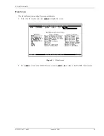
Page 69: ... 6 2003 59 Help Screen Provides information on using the screens and menus 1 Select the Help option and press to display the screen Figure 51 Help Screen 2 Press to return to the DICOLU main screen or to return to the PAU PMU main menu ENTER ESC CTRL R ...

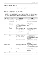
Page 70: ...oo much power or has a ground fault Check the HDSL loop for shorts or grounds On OK Flashing The PLL 735 detects the RT but the HDSL loop cannot synchronize Check the HDSL loop for faults such as shorts grounds or bridged taps Verify loop length limitations are not exceeded Off No battery feed to COT shelf Verify fuses in equipment bay fuse panel Verify CO battery is present on COT shelf backplane...

Page 71: ... On There is a problem with the PLL 735 Replace the PLL 735 Flashing The PLL 735 or RT has generated an alarm Connect VT 100 terminal to PAU or PMU The PLL 735 main screen will indicate the cause of the alarm Correct the condition causing the alarm Off OK LED Color State Probable Cause Solution ...

Page 72: ...peration of the COLU Check the front panel LEDS for flashing while line is ringing If you cannot view the COLU Main Screen a communication error exists indicating a faulty COLU Remove and re insert the COLU 2 Go to the Test option and select the desired circuit to test 3 View the SDT results Refer to the Test Submenu section for specific results 4 At the RTs check for ringing with the RJ 11 test j...

Page 73: ...ent 2 Call or write ADC s RMA Department to ask for an RMA number and any additional instructions Use the telephone number fax number or email address listed below Telephone 800 366 3891 Email Address rma ADC com 3 Include the following information in writing along with the equipment you are returning Company name and address Contact name and telephone number The shipping address to which ADC shou...

Page 74: ...rite ADC s address and the RMA Number you received from the RMA Department clearly on the outside of the carton and return to ADC DSL Systems Inc 14352 Franklin Ave Tustin CA 92780 7013 Attention RMA Number If the equipment is defective please tell us what you observed just before the equipment malfunctioned Be as detailed in your description as possible All shipments are to be returned prepaid AD...

Page 75: ...ate radio frequency energy and if not installed and used in accordance with the instruction manual may cause harmful interference to radio communications Operation of this equipment in a residential area is likely to cause harmful interference in which case the use will be required to correct the interference at his own expense Modifications The FCC requires the user to be notified that any change...

Page 76: ...grated Central Office Line Unit ES Errored Seconds HDSL High bit rate Digital Subscriber Line LCFO Line Current Feed Open LED Light Emitting Diode LOSW HDSL Loss of Synchronization Word MAR HDSL Line Margin MISPWRn Power n Missing MJ Major MLT Mechanized Loop Testing MN Minor MISMATCHn COLU RT Mismatch NA Not Alarmed NORLUSWn NO RT n Software NR Not Reported PAU PG Plus Alarm Unit PFO Power Feed O...

Page 77: ...735 010 03H Acronyms PLL 735 Lists 1 2 and 3 January 6 2003 67 RMA Return Materials Authorization RT Remote Terminal enclosure for the RLU SDT Subscriber Drop Test SYNC Synchronization UAS Unavailable Seconds ...

Page 78: ...World Headquarters ADC Telecommunications Inc 12501 Whitewater Drive Minnetonka Minnesota USA 55343 For Technical Assistance 800 366 3891 So 5B 1251795 ...

Reviews: