background image

SCP-AMU912-010-06H

July 19, 2004

50

ADC Telecommunications, Inc.

2

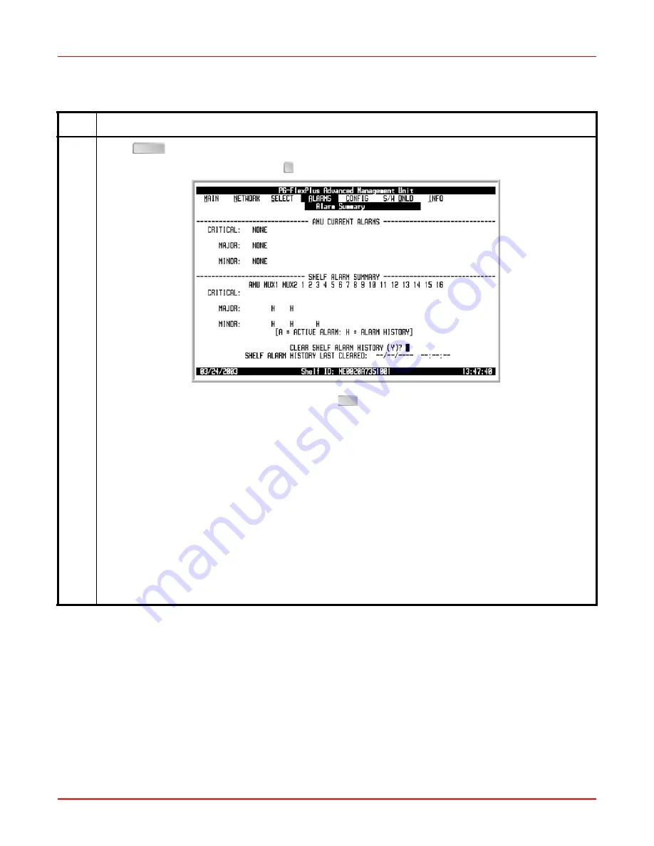
Press 

. The following screen appears.

To clear the shelf alarm history, press 


at the 

CLEAR SHELF ALARM HISTORY (Y)?

 prompt. 

If you want to retain the shelf alarm history, press 

. The Main Menu screen reappears.

The alarm information displayed indicates:
Alarm Types:

• CRITICAL 

Critical alarm is present

• MAJOR 

Major alarm is present

• MINOR 

Minor alarm is present

• NOT ALARMED

Condition is active, but has no severity

• NOT REPORTED Condition not reported by system

Alarm States:

• A

Designates active alarm

• H

Designates history alarm

ALARMS — Alarms Summary (Continued)

Step

Action

ENTER

Y

ESC

Summary of Contents for PG-FlexPlus AMU-912

Page 1: ...Section SCP AMU912 010 06H PG FlexPlus Advanced Management Unit Technical Practice Model List CLEI Code AMU 912 1 VAC2Z7HL ...

Page 2: ......

Page 3: ...whole or in part without the written consent of ADC Contents herein are current as of the date of publication ADC reserves the right to change specifications at any time without notice Information furnished by ADC is believed to be accurate and reliable In no event shall ADC be liable for any damages resulting from the loss of data loss of use or loss of profits and ADC further disclaims any and a...

Page 4: ...s original container Element Meaning Bold font Text that you must input exactly as shown e g type 1 for card 1 menu buttons e g ACCEPT SHELF OPTIONS or menu screen options e g ALARMS screen that you must select Italic font Variables that you must determine before inputting the correct value e g Password Monospace font References to screen prompts e g Invalid Password Try Again Reader Alert Meaning...

Page 5: ...ed Data Link 9 Specifications 10 Front Panel 11 Installation and Test 13 Installation 13 Install a AMU 912 13 Initialize and Power Up the AMU 912 13 ACO Pushbutton 13 Administration 14 Front Panel Craft Port to Terminal Connections 14 Front Panel Craft Port to Modem Connections 15 Backplane Craft Port to Terminal Connections 16 Backplane Craft Port to Modem Connections 17 CONNECTING OVER TELNET 19...

Page 6: ...gh COLU 16 47 Alarm Menu Options 48 ALARMS Alarms Summary 49 ALARMS Alarm History 52 ALARMS Service Loss Alarm History 54 ALARMS Environmental Alarm History 56 ALARMS Relay Summary 58 ALARMS LED Summary 60 ALARMS Activate ACO 61 Configuration Menu Options 63 CONFIG Shelf Options 66 CONFIG IP INFO 72 CONFIG SNMP GATEWAY INFO 75 CONFIG SNMP COMMUNITY INFO 79 CONFIG Password 81 CONFIG Alarm Types 84 ...

Page 7: ...th Modem 107 Modem Connected to PC 107 Modem Connected to System 107 Error Messages 108 Information Menu Options 109 INFO Inventory 110 INFO Help 111 Acronyms 113 Product Support 115 Technical Support 115 Limited Warranty 115 Returns 115 FCC Class A Compliance 116 Modifications 116 ...

Page 8: ...SCP AMU912 010 06H July 19 2004 vi ADC Telecommunications Inc ...

Page 9: ...inal Connections 14 Figure 7 Front Panel Craft Port to Modem Connections 15 Figure 8 Backplane Craft Port to Terminal Connections Using a Null Modem Cable 16 Figure 9 Backplane Craft Port to Modem Connections 17 Figure 10 Isolated LAN Model 20 Figure 11 MSLAN Connection to Hub Switch 21 Figure 12 MSLAN Connection with Different Segment Unrestricted Route Model 22 Figure 13 MSLAN Connection with Di...

Page 10: ...SCP AMU912 010 06H July 19 2004 viii ADC Telecommunications Inc ...

Page 11: ...e 14 Example of Connection to Router Different Segment Unrestricted Route 23 Table 15 Example of Connection to Router Different Segment Restricted Route 25 Table 16 Navigational Keystrokes 26 Table 17 Main Menu Options 30 Table 18 Shelf Summary 32 Table 19 Network Menu Options 38 Table 20 Alarm Menu Options 48 Table 21 Configuration Menu Options 64 Table 22 Shelf Options 70 Table 23 IP Information...

Page 12: ...SCP AMU912 010 06H July 19 2004 x ADC Telecommunications Inc Table 36 Information Menu Options 109 Table 37 Fault Isolation and Troubleshooting 112 ...

Page 13: ...s multiple shelves to be connected together This allows all the cascaded shelves to be managed from a single interface point Up to 24 shelves can be connected together through the 10Base 2 connector on the shelf backplane The AMU 912 provides two management user interfaces VT 100 screens based user interface SNMP Element Management System EMS Stargazer user interface You can provision monitor and ...

Page 14: ...on using a 10Base 2 one for a user interface using a 10Base T Ethernet connection in accordance with IEEE standard 802 3 10Base 2 System uses COAX interconnects terminated with BNC connectors on the backplane of the shelf unit Shelves are cascaded in a daisy chain configuration 10Base 2 must be terminated on both ends with 50Ω terminations Allows SNMP operations 10Base T Standard RJ 45 Ethernet co...

Page 15: ...y the on board test unit located in the RT are presented as pass fail on the Craft interface Test results are not provided as DC resistive signatures for a screen initiated drop test Table 1 DC Resistive Signatures Test Failure Condition TR kΩ TG RG kΩ RT Equipment Failure RT detected but no response from RT 17 8 90 9 Foreign Voltage on Drop TG or RG 10 Vrms TG or RG 6 Vdc 27 8 90 9 All Tests OK N...

Page 16: ...testing on the Integrated system the AMU 912 provides the diode 410Ω bypass integrity test signature as required by TR 08 Additionally subscriber drop test results are provided as TA 909 DC resistive signatures as shown in Table 1 on page 3 by the AMU 912 to the Test Tip and Test Ring terminals on the backplane Figure 2 DC Resistive Signatures Mechanized Loop Test System Loop Maintenance Operating...

Page 17: ...rts baud rate 1200 2400 4800 9600 19200 38400 57600 115200 configured as DCE supporting Transmit Receive DTR and DSR signals 9 pin DB type connector An RS 232 serial interface is provided on the shelf backplane and meets the following specifications compliant with EIA RS 232 full duplex serial asynchronous format supports baud rate 1200 2400 4800 9600 19200 38400 57600 115200 configured as DTE sup...

Page 18: ...d when any visual alarm is active in the shelf The AMU 912 can also accept external environmental alarms via the backplane DB 25 connector however the functionality of the DB 25 must be changed to ENV ALARMS setting rather than the default setting of CRAFT PORT refer to CONFIG Shelf Options on page 66 The DB 25 connector can function as a craft access port or operate as an external alarm input sou...

Page 19: ...h the Derived Data Link DDL of the TR08 Shelf A DS1 There are three shelf alarm relay settings Standard Telemetry and Environmental The system activates different relays depending on Shelf Option configuration Table 3 on page 8 Refer to Figure 4 and Table 4 on page 8 for proper wiring of customer supported DB 25 alarm cable Figure 4 ENV Alarm Input Pinouts An alarm type set to NA will accumulate h...

Page 20: ...WRMISC ENV2 ENV2 SYS2 PWRMISC Door Alarm COM MN ENV3 ENV3 COM MN Fan Alarm COM MN ENV4 ENV4 COM MJ MISC COM MJ Standard Telemetry Environmental System ID Shelf ID System ID Critical Visual System Major Critical Visual Critical Audible System Minor Major Visual Major Visual Major Visual Minor Visual Major Audible Major Audible Environmental 1 Minor Visual Minor Visual Environmental 2 Minor Audible ...

Page 21: ...he type of alarm is determined by the CO Line Unit type that has the Active Service Loss Alarm e g Shelf A B C or D alarms are only reported against the FLL 814 The severity and CO Line Unit location of the Service Loss Alarm will determine what TR 08 alarm is reported Refer to Table 5 and Table 6 Table 5 Service Loss Alarm Reporting Table 6 Alarms Reported for each Different COLU Service Loss Ala...

Page 22: ...95 non condensing Physical Height 5 5 in 14 0 cm Width 1 1 in 2 8 cm Length 10 5 in 26 7 cm Weight 0 7 lbs 0 3 kg Alarm Relays Critical Audible Visual Major Audible Visual Minor Audible Visual Shelf ID Visual Alarm Relay Contact Rating 0 3 A 125 Vac 0 3 A 110 Vdc 1 0 A 30 Vdc Alarm Cutoff ACO pushbutton N A ACO LED Remote ACO capabilities Test VF Drop Connector RJ 11 RS 232 Connectors DB 9 female ...

Page 23: ...ont panel and Table 8 on page 12 lists the LEDs and LED status for the AMU 912 Table 9 on page 12 lists the LED indications for the AMU 912 diagnostic and maintenance modes Figure 5 AMU 912 Front Panel Status LEDs Alarm Cutoff Switch Analog Test Jack Craft Port 10Base T Ethernet Connector Retaining Latch ...

Page 24: ...active in shelf Off No Minor alarms active ACTIVE Green Flashing Ethernet activity Off No Ethernet activity COM Green On Multishelf management is active Off Multishelf management is not active FAULT Red On Replace the AMU 912 Off No fault detected ACO Yellow On ACO activated Off ACO not activated LED State Description Action PWR LED On All other LEDs Flashing AMU 912 is running in Boot Mode Applic...

Page 25: ...e ACO LED goes off ATTENTION STATIC SENSITIVE DEVICE DO NOT HANDLE ANY MATERIAL WITHOUT FIRST TAKING PROPER STATIC CONTROL PRECAUTIONS The AMU 912 must be installed in the slot labeled COMMON Refer to the documentation accompanying the shelf for information on MUX and line unit numbering Step Action 1 Open the retaining latch at the front bottom of the card 2 Insert the AMU 912 into the card guide...

Page 26: ... AMU 912 front panel or shelf backplane The VT 100 interface allows real time updating of information displayed on the screen Through the craft interface screens system administration functions such as alarm checking and clearing configuration changes performance monitoring and testing can be performed FRONT PANEL CRAFT PORT TO TERMINAL CONNECTIONS Connections between the RS 232 craft port of the ...

Page 27: ...le should be used Ensure that the modem s Carrier Detect CD and DTR functions are enabled This allows the modem connection to terminate properly when the AMU 912 drops Data Set Ready DSR and the unit logs off after the modem drops CD The following connections are required to make the modem work correctly Figure 7 Figure 7 Front Panel Craft Port to Modem Connections ...

Page 28: ...MINAL CONNECTIONS Use a null modem cable to connect to a Data Terminal Equipment DTE device from the backplane connector Figure 8 shows the wiring for the required null modem cable to a DB 9 and a DB 25 connector Figure 8 Backplane Craft Port to Terminal Connections Using a Null Modem Cable ...

Page 29: ...er Equipment DCE DB 25 connector Figure 9 Backplane Craft Port to Modem Connections Refer to Table 10 to set up the VT 100 craft port connections and Table 11 on page 18 for VT 100 Modem settings Table 10 Craft Port Configuration Control Setting Supported Default Software Flow Control XON XOFF Enabled Enabled Baud Rate 1200 2400 4800 9600 19200 38400 57600 115200 Autobaud Asynchronous Communicatio...

Page 30: ...tions Inc Table 11 Modem Settings Control Setting Supported Hardware Flow Control Off Software Flow Control XON XOFF Enabled Baud Rate 1200 2400 4800 9600 19200 38400 57600 115200 Asynchronous Communication Parameters Data Bits 8 Parity None Stop Bits 1 ...

Page 31: ...pendent upon its physical connections An MSLAN can support from one to a maximum or 24 AMU 912s on a single segment There are two different methods for connecting one or more AMU 912s to a MSLAN The preferred recommended method to connect an MSLAN consists of one or more shelves connected by means of 10Base 2 cabling and connectors on their respective backplanes Each end of the daisy chained LAN m...

Page 32: ...IP Address Default Route Default Route Mask Results Shelf A AMU 912 172 17 0 3 255 255 0 0 0 0 0 0 0 0 0 0 0 0 0 0 Defines that the AMU 912 exists on the 172 17 xxx xxx network and responds only to requests originating from this network Thus the following clients may or may not communicate with the the target AMU 912 TELNET Client 1 172 17 20 9 255 255 0 0 Able to communicate with target Shelf A A...

Page 33: ...itch Same Segment Entity IP Address Subnet Mask Gateway IP Address Default Route Default Route Mask Results Shelf A AMU 912 172 17 0 3 255 255 0 0 0 0 0 0 0 0 0 0 0 0 0 0 Defines that the AMU 912 exists on the 172 17 xxx xxx network and responds only to requests originating from this network Thus the following clients may or may not communicate with the the target AMU 912 TELNET Client 1 172 17 20...

Page 34: ...is is accomplished by configuring a gateway router to which the AMU 912 can direct its reply packets You can access these values from the CONFIG IP INFO on page 72 The gateway IP address must be accessible from the MSLAN and the Default Route and Default Route Mask fields must have the value of 000 000 000 000 Figure 12 MSLAN Connection with Different Segment Unrestricted Route Model Shelf 1 10Bas...

Page 35: ...he following clients may or may not communicate with the the target AMU 912 TELNET Client 1 172 17 20 9 255 255 0 0 172 17 0 1 Able to communicate with target Shelf A AMU 912 TELNET Client 2 172 10 20 9 255 255 0 0 172 10 0 1 Able to communicate with target Shelf A AMU 912 provided that 172 10 xxx xxx is accessible by the gateway device TELNET Client 3 128 33 20 9 255 255 0 0 0 0 0 0 Unable to com...

Page 36: ...articular network CONFIG IP INFO on page 72 Refer to Table 15 on page 25 Configure a gateway router to which the AMU 912 can direct its reply packets The gateway IP address must be accessible from the MSLAN Configure the Default Route and Default Route Mask fields to the values of the external Network to which accessibility is granted Figure 13 MSLAN Connection with Different Segment Restricted Ro...

Page 37: ...eway The addition of a Specified Default Route and Default Route Mask limits the accessibility of remote connections as follows below TELNET Client 1 172 17 0 10 255 255 0 0 172 17 0 1 Host IP network of 172 17 xxx xxx matches the AMU 912 s network of 172 17 xxx xxx and is accessible TELNET Client 2 172 2 0 11 255 255 0 0 172 2 0 1 The Host IP network of 172 2 xxx xxx does NOT match the AMU 912 s ...

Page 38: ...field No effect Cycle through the field options Moves up a menu level From the Main Menu the Logout screen is displayed Returns to Main Menu without accepting changes The banner briefly appears and then the Main Menu bar displays Returns to the Main Menu The banner briefly appears and then the Main Menu bar displays Returns to Main Menu without accepting changes keys Selects an underlined or highl...

Page 39: ...ND DISPLAY STRUCTURE Figure 14 shows the menu structure of the terminal management system Figure 14 Terminal Menu and Display Structure Test Access Logout Shelf Summary MultiShelf Access Connection Summary MUX 1 MUX 2 COLU 1 COLU 2 COLU 15 COLU 16 Alarm Summary Alarm History Service Loss Alarm History Environmental Alarm History Relay Summary LED Summary Activate ACO Shelf Options IP Info Set Fact...

Page 40: ...al Support while at the terminal Technical Support will provide a temporary password based on the Access Key number displayed on the Logon screen Log On the AMU 912 Step Action 1 Press several times to activate the Autobaud feature When the Login screen displays type the Password then press 2 If an invalid Password is entered the Login screen is redisplayed with the message Invalid Password Try Ag...

Page 41: ...4 SCP AMU912 010 06H ADC Telecommunications Inc 29 3 After a successful login the welcome banner screen appears for a few seconds Then the AMU 912 Main Menu screen appears Log On the AMU 912 Continued Step Action ...

Page 42: ...le 17 Main Menu Options Sub Menu Options Sub Menu Descriptions Parameters Valid Values Shelf Summary Shelf Summary shelf unit types and alarm status Test Access Allows you to perform test access on individual channels in the shelf Channel Unit cards DS1 Number Channel Number Test Access Is Currently Active On Channel Of DS1 Of MUX COLU Would You Like To End Test Access On MUX1 Y N 1 8 1 24 Y or N ...

Page 43: ...lf unit types and alarm status of the system Refer to Table 18 on page 32 for Shelf Summary information MAIN Shelf Summary Step Action 1 At the Main Menu screen select MAIN Press to choose Shelf Summary The following screen appears 2 Press The following screen appears 3 Press The Main Menu screen reappears ENTER ESC ...

Page 44: ...scription Shelf Unit Types SLOT Slot identifier name or number UNIT TYPE Identifier for card type or not equipped note Shelf Current Alarms CRITICAL Summary of Critical alarms for each shelf slot MAJOR Summary of Major alarms for each shelf slot MINOR Summary of Minor alarms for each shelf slot ...

Page 45: ...al channels in the shelf Channel Unit cards MAIN Test Access Step Action 1 At the Main Menu screen select MAIN Press to choose Test Access The following screen appears 2 Press The following screen appears Highlight the applicable entity MUX1 MUX 2 COLU1 through COLU16 per your system configuration As an example we have chosen MUX1 ENTER ...

Page 46: ...er 1 8 and Channel Number 1 24 Select ENABLE TEST ACCESS and press 4 To start the test press from the flashing Test Access On Channel of DS1 of MUX COLU Has Started Hit CR To Resume Screens prompt If you do not want to start the test press MAIN Test Access Continued Step Action ENTER ENTER ESC ...

Page 47: ...ccess Is Currently Active On Channel Of DS1 Of MUX COLU Would You Like To End Test Access On MUX COLU Y N prompt Then press The Main Menu screen will reappear To let the test continue to run type from the Test Access Is Currently Active On Channel Of DS1 Of MUX COLU Would You Like To End Test Access On MUX COLU Y N prompt The Main Menu screen reappears MAIN Test Access Continued Step Action Y ENTE...

Page 48: ...ave your VT 100 terminal unattended for any length of time log off until you are ready to resume work This prevents unauthorized persons from inadvertently changing any of your operating parameters and causing a possible loss of service At the Main Menu screen select MAIN Press to choose Logout The following screen appears 2 Press The following screen appears ENTER ...

Page 49: ...July 19 2004 SCP AMU912 010 06H ADC Telecommunications Inc 37 3 Press The Login screen appears MAIN Logout Continued Step Action Y ...

Page 50: ...Menu Options Sub Menu Options Sub Menu Descriptions MultiShelf Access View all accessible Management Units AMU 912s PMU 712s existing on the 10Base 2 LAN Connection Summary View all incoming MultiShelf connections maximum of 3 Local Summary View the Local Card Summary for the AMU 912 includes card identification information port session locations and states and alarm activity Inband Traffic Summar...

Page 51: ...ultiShelf Access This screen displays a list of all accessible Management Units AMU 912s and PMU 712s existing on the 10Base 2 LAN NETWORK MultiShelf Access Step Action 1 At the Main Menu screen select NETWORK Press to choose MultiShelf Access The following screen appears ...

Page 52: ...sociated DISPLAY option The following screen type appears To return to the previous screen select PREVIOUS SCREEN and press To connect to another AMU 912 or PMU 712 select CONNECT from either of the above two screens You will see the Welcome Banner screen for a few seconds then you are connected to the card AMU 912 or PMU 712 that you chose NETWORK MultiShelf Access Continued Step Action ENTER ENT...

Page 53: ...communications Inc 41 3 When you log out of the card AMU 912 or PMU 712 selected in Step 2 you get this screen Press The following screen appears 4 Press The Main Menu screen reappears NETWORK MultiShelf Access Continued Step Action ENTER ESC ...

Page 54: ...g up to three simultaneous inbound connections NETWORK Connection Summary Step Action 1 At the Main Menu screen select NETWORK Press to choose Connection Summary The following screen appears If there is no information in the Connection Summary the above screen displays a flashing message at the bottom of the screen Connection Table Empty Hit CR to Continue Press The Main Menu screen reappears 2 Pr...

Page 55: ...r the AMU 912 including card identification information port session locations and states and alarm activity NETWORK Local Summary Step Action 1 At the Main Menu screen select NETWORK Press to choose Local Summary The following screen appears 2 Press The following screen appears 3 Press The Main Menu screen reappears ENTER ESC ...

Page 56: ... individual network DS1 ports NETWORK Inband Traffic Summary Step Action 1 At the Main Menu screen select NETWORK Press to choose Inband Traffic Summary The following screen appears 2 Press The following screen appears To clear inband traffic counts press To retain the existing inband traffic counts press The Main Menu screen reappears ENTER Y ESC ...

Page 57: ... To clear the inband traffic counts press at the ALL INBAND TRAFFIC COUNTS WILL BE CLEARED CONTINUE Y N prompt All inband traffic counts are cleared To retain the existing inband traffic counts press 4 Press The Main Menu screen reappears NETWORK Inband Traffic Summary Continued Step Action Y N ESC ...

Page 58: ...SCP AMU912 010 06H July 19 2004 46 ADC Telecommunications Inc SELECT MENU OPTIONS The Select Menu allows you to select any of the cards MUX 1 or MUX 2 COLU 1 through COLU 16 installed in the shelf ...

Page 59: ...talled in the shelf SELECT MUX 1 or MUX 2 COLU 1 Through COLU 16 Step Action 1 At the Main Menu screen choose SELECT Press to choose MUX 1 or the appropriate choice per your system configuration The following screen appears 2 Press The following screen type appears The above example is the AMX 944 Main Menu screen 3 Press repeatedly if needed until the AMU 912 Main Menu screen reappears ENTER ESC ...

Page 60: ... Will Be Cleared Continue Y N Y Y or N Alarm History View the AMU 912 alarm status Clear AMU Alarm History Y AMU Alarm History Will Be Cleared Continue Y N Y Y or N Service Loss Alarm History View the service loss alarm status for all COLUs in the shelf Service Loss Alarm History will be cleared Continue Y N Y or N Environmental Alarm History View the status of environmental alarmed events Clear E...

Page 61: ...ations Inc 49 ALARMS Alarms Summary This screen displays the AMU 912 MUXs and COLUs critical major and minor alarms ALARMS Alarms Summary Step Action 1 At the Main Menu screen select ALARMS Press to choose Alarms Summary The following screen appears ...

Page 62: ...arm history press The Main Menu screen reappears The alarm information displayed indicates Alarm Types CRITICAL Critical alarm is present MAJOR Major alarm is present MINOR Minor alarm is present NOT ALARMED Condition is active but has no severity NOT REPORTED Condition not reported by system Alarm States A Designates active alarm H Designates history alarm ALARMS Alarms Summary Continued Step Act...

Page 63: ...clear the shelf alarm history press at the SHELF ALARM HISTORY WILL BE CLEARED CONTINUE Y N prompt If you want to retain the shelf alarm history press then press The Main Menu screen reappears 4 Press The Main Menu screen reappears ALARMS Alarms Summary Continued Step Action Y N ESC ESC ...

Page 64: ...ain Menu screen select ALARMS Press to choose Alarm History The following screen appears 2 Press The following screen appears To clear the AMU 912 alarm history press at the CLEAR AMU ALARM HISTORY Y prompt If you want to retain the AMU 912 alarm history press The Main Menu screen reappears The status OK displays in the Current column when the alarm is not present The status Active displays when a...

Page 65: ...ate that the registers were last cleared are updated If you want to retain the AMU 912 alarm history press then press The Main Menu screen reappears Clearing the alarm history does not clear any alarm that is currently active in the system If there is an active alarm the count is set to 1 and the value in the LAST date and time field is set to the FIRST date and time field 4 Press The Main Menu sc...

Page 66: ...ction 1 At the Main Menu screen select ALARMS Press to choose Service Loss Alarm History The following screen appears 2 Press The following screen appears To view other page s select View Other Page button then press To clear the service loss alarm history select Clear Service Loss Alarm History button then press The status OK displays in the Current column when the alarm is not present The status...

Page 67: ...e that the registers were last cleared are updated If you want to retain the existing alarm history press then press The Main Menu screen reappears Clearing the alarm history does not clear any alarm that is currently active in the system If there is an active alarm the count is set to 1 and the value in the LAST date and time field is set to the FIRST date and time field 4 Press The Main Menu scr...

Page 68: ... Menu screen select ALARMS Press to choose Environmental Alarm History The following screen appears 2 Press The following screen appears To clear the environmental alarm history press at the CLEAR ENVIRONMNENTAL ALARM HISTORY Y prompt If you want to retain the environmental alarm history press The Main Menu screen reappears The status OK displays in the Current column when the alarm is not present...

Page 69: ...that the registers were last cleared are updated If you want to retain the existing environmental alarm history press then press The Main Menu screen reappears Clearing the alarm history does not clear any alarm that is currently active in the system If there is an active alarm the count is set to 1 and the value in the LAST date and time field is set to the FIRST date and time field 4 Press The M...

Page 70: ...ys the system relay summary ALARMS Relay Summary Step Action 1 At the Main Menu screen select ALARMS Press to choose Relay Summary The following screen appears 2 Press The following screen appears The alarm information displayed indicates ACTIVE Relay is activated INACTIVE Relay is not activated ENTER ...

Page 71: ...July 19 2004 SCP AMU912 010 06H ADC Telecommunications Inc 59 3 Press The Main Menu screen reappears ALARMS Relay Summary Continued Step Action ESC ...

Page 72: ... LED activity ALARMS LED Summary Step Action 1 At the Main Menu screen select ALARMS Press to choose LED Summary The following screen appears 2 Press The following screen appears The alarm information displayed indicates ON LED is on OFF LED is off FLASHING LED is flashing 3 Press The Main Menu screen reappears ENTER ESC ...

Page 73: ...ecommunications Inc 61 ALARMS Activate ACO This screen allows you to activate the AMU 912 Alarm Cutoff feature ALARMS Activate ACO Step Action 1 At the Main Menu screen select ALARMS Press to choose Activate ACO The following screen appears ...

Page 74: ...ommunications Inc 2 Press The following screen appears To activate the ACO press at the ACO WILL BE ACTIVATED Y prompt Press The Main Menu appears To refrain from activating the ACO press ALARMS Activate ACO Continued Step Action ENTER Y ENTER N ...

Page 75: ...ications Inc 63 CONFIGURATION MENU OPTIONS The Configuration Menu provides access to system provisioning and setting all options to factory defaults etc Refer to Table 21 on page 64 for sub menu options and descriptions parameters and valid values ...

Page 76: ...ges Community Access Privileges Password Personal identifier for security reasons Enter Old Password and Press Return Enter New Password and Press Return Enter Password Again and Press Return This Password will be permanently changed Continue Y N 6 to 10 characters Embedded spaces not allowed Case insensitive and must contain at least 1 alpha character i e A Z 1 numeric character i e 1 9 and 1 spe...

Page 77: ...ime Month Day Year Hour Minute Seconds January December 1 31 2002 accepts any 4 number year between 2000 2069 00 24 0 59 0 59 Set Factory Defaults Reset the provisionable items to the original factory settings Configuration data will be set to factory defaults This May Be Service Affecting Continue Y N Configuration data has been set to factory defaults Press ESC to continue Y or N ESC Sub Menu Op...

Page 78: ... Shelf Options CONFIG Shelf Options Step Action 1 At the Main Menu screen select CONFIG Press to choose Shelf Options The following screen appears 2 Press The following screen appears To change a field value press to toggle to the desired value or press or to move to the next option To save the shelf options select the ACCEPT SHELF OPTIONS button then press ENTER SPACEBAR ENTER ...

Page 79: ... 67 3 From the SHELF OPTIONS WILL BE CHANGED CONTINUE Y N prompt the following actions can be taken To save the shelf options press All current values are set to desired values To retain the existing values press CONFIG Shelf Options Continued Step Action Y N ...

Page 80: ...w the rest of the shelf options select the SHOW MORE SHELF OPTIONS button 5 To change the field value press to toggle to the desired value To save the shelf option select the ACCEPT SHELF OPTIONS button then press CONFIG Shelf Options Continued Step Action SPACEBAR ENTER ...

Page 81: ...OPTIONS WILL BE CHANGED CONTINUE Y N prompt the following actions can be taken To save the shelf option press The current value is set to the desired value To retain the existing value press 7 Press The Main Menu screen reappears CONFIG Shelf Options Continued Step Action Y N ESC ...

Page 82: ...cally set to ENV ALARMS when the AMU 912 is plugged into a field shelf and the automatic field shelf provisioning option is set to ENABLED ENV ALARMS Rear DB 25 connector is setup to provide EXT environmental alarm inputs Allow Automatic Provisioning of AMU Options Plugged into a Field Shelf ENABLED Allows automatic provisioning when the AMU 912 is plugged into a field shelf When enabled the setti...

Page 83: ...NTAL when the AMU 912 is plugged into a field shelf and the automatic field shelf provisioning option is set to ENABLED TELEMETRY Alarm relay terminations on the shelf backplane support the following alarms Shelf ID System Major System Minor Major Visual Major Audible Minor Visual Minor Audible ENVIRONMENTAL Alarm relay terminations on the shelf backplane support the following alarms System ID Cri...

Page 84: ...s is changed the AMU 912 will perform a warm reset CONFIG IP INFO Step Action 1 At the Main Menu screen select CONFIG Press to choose IP Info The following screen appears 2 Press The following screen appears To change a field value press to toggle to the desired value or press or to move to the next option Type the desired values To save the shelf options select the ACCEPT IP CHANGES button then p...

Page 85: ...U IP INFO IS CHANGED THE AMU WILL BE RESET CONTINUE Y N prompt the following actions can be taken To change the IP Info and reset the AMU 912 press All current values are set to desired values To retain the existing values press 4 Press The Main Menu screen reappears CONFIG IP INFO Continued Step Action Y N ESC ...

Page 86: ...ion AMU IP Address Unique 4 byte address AMU Subnet Mask Subnet mask assigned to the LAN Gateway IP Address Optional Unique 4 byte address of the gateway router bridge Default Route Optional Network address assigned to the external LAN Default Route Mask Optional Subnet Mask assigned to the external LAN ...

Page 87: ...red as a trap recipient If you disable gateway functionality the AMU is not a manageable node via SNMP and will not forward trap notifications Refer to Table 24 on page 78 for SNMP Gateway Information This procedure shows how to enable gateway functionality Once the gateway is enabled it works the same way to disable the gateway functionality CONFIG SNMP GATEWAY INFO Step Action 1 At the Main Menu...

Page 88: ...4 76 ADC Telecommunications Inc 2 Press The following screen appears To enable gateway functionality press To leave gateway disabled press The Main Menu screen reappears CONFIG SNMP GATEWAY INFO Continued Step Action ENTER ENTER ESC ...

Page 89: ...3 The following actions can be taken To enable gateway functionality press at the SNMP GATEWAY OPTION WILL BE CHANGED CONTINUE Y N prompt To leave gateway disabled press 4 Press The Main Menu screen reappears CONFIG SNMP GATEWAY INFO Continued Step Action Y N ESC ...

Page 90: ...teway Description Default ENABLE Configured as a manageable SNMP node and receives trap notification from all AMUs on its network then forwards traps to the IP Address that is configured as a trap recipient DISABLE DISABLE AMU is not a manageable node via SNMP and will not forward trap notifications ...

Page 91: ...must match the Element Manager Refer to Table 25 on page 80 for SNMP Community Information CONFIG SNMP COMMUNITY INFO Step Action 1 At the Main Menu screen select CONFIG Press to choose SNMP Community Info The following screen appears 2 Press The following screen appears To change a field value press or to move to the correct option Type the desired values To apply SNMP changes select the ACCEPT S...

Page 92: ...80 ADC Telecommunications Inc Table 25 SNMP Community Information Communities Description Default Read Only SNMP community string for read only privileges adcpublic Read Write SNMP community string for read write privileges adcprivate ...

Page 93: ... This screen allows you to change the Password for security reasons Refer to Table 21 on page 64 for valid values CONFIG Password Step Action 1 At the Main Menu screen select CONFIG Press to choose Password The following screen appears 2 Press The following screen appears ENTER ...

Page 94: ...3 Enter the current old Password System Default is password 1 For security reasons the system echoes the password with Press The following screen appears 4 Enter the new Password Press The following screen appears CONFIG Password Continued Step Action ENTER ENTER ...

Page 95: ...creen appears 6 The following actions can be taken a From The Password will be permanently changed Continue Y N prompt the following actions can be taken To accept the new password press To retain the existing password press 7 Press The Main Menu screen reappears CONFIG Password Continued Step Action ENTER Y N ESC ...

Page 96: ...alarm types Table 27 on page 87 shows the alarm fields values descriptions and default settings Table 26 on page 86 provides a description of the Alarm types reported CONFIG Alarm Types Step Action 1 At the Main Menu screen select CONFIG Press to choose Alarm Types The following screen appears 2 Press The following screen appears ENTER ...

Page 97: ...ave the alarm type changes select the ACCEPT ALARM TYPE CHANGES button then press From the AMU ALARM TYPE CHANGES WILL BE CHANGED CONTINUE Y N prompt the following actions can be taken To save the alarm type changes press All current values are set to desired values To retain the existing alarm types press 4 Press The Main Menu screen reappears CONFIG Alarm Types Continued Step Action SPACEBAR ENT...

Page 98: ...munications Inc Table 26 Alarm Types Reported Settings Alarm LED Lit Main Shelf Summary History Updated SNMP Trap CR Critical Yes Yes Yes Yes MJ Major Yes Yes Yes Yes MN Minor Yes Yes Yes Yes NA Not Alarmed No No Yes Yes NR Not Reported No No No No ...

Page 99: ...ng A 48 V battery MJ Power B Missing CR MJ MN NA NR AMU 912 has detected missing B 48 V battery MJ EEPROM Failure CR MJ MN NA NR Non volatile database is corrupt MN Invalid MAC Address CR MJ MN NA NR AMU 912 has an invalid MAC address MN Duplicate MAC Address CR MJ MN NA NR AMU 912 has the same MAC address as another AMU 912 connected to the 10BASE 2 backplane network MN ...

Page 100: ...ioned Table 28 on page 90 shows the service loss alarm fields values descriptions and default settings Table 26 on page 86 provides a description of the alarm types reported CONFIG Service Loss Alarm Types Step Action 1 At the Main Menu screen select CONFIG Press to choose Service Loss Alarm Types The following screen appears 2 Press The following screen appears ENTER ...

Page 101: ...es select the ACCEPT SERVICE LOSS ALARM TYPE CHANGES button then press From the SERVICE LOSS ALARM TYPE CHANGES WILL BE CHANGED CONTINUE Y N prompt the following actions can be taken To save the service loss alarm type changes press All current values are set to desired values To retain the existing service loss alarm types press 4 Press The Main Menu screen reappears CONFIG Service Loss Alarm Typ...

Page 102: ...0 06H July 19 2004 90 ADC Telecommunications Inc Table 28 Service Loss Alarm Types Alarms Value Description Default Service Loss COLUn where n 1 16 CR MJ MN NA NR Service to an RT serviced by a COLU has been lost MJ ...

Page 103: ...be provisioned for each environmental alarm Table 29 on page 93 shows the environmental alarm setup fields values descriptions and default settings CONFIG Environmental Alarms Setup Step Action 1 At the Main Menu screen select CONFIG Press to choose Environmental Alarms Setup The following screen appears 2 Press The following screen appears ENTER ...

Page 104: ... select the ACCEPT ENVIRONMENTAL ALARM TYPE CHANGES button then press From the ENVIRONMENTAL ALARM TYPE CHANGES WILL BE CHANGED CONTINUE Y N prompt the following actions can be taken To save the environmental alarm type changes press All current values are set to desired values To retain the existing environmental alarm types press 4 Press The Main Menu screen reappears CONFIG Environmental Alarms...

Page 105: ... Reported via the system 1 MN bit SYS1 MJ Reported via the system 1 MJ bit SYS2 PWRMISC Reported via the system 2 PWR MISC bit SYS2 MN Reported via the system 2 MN bit SYS2 MJ Reported via the system 2 MJ bit COM PWRMISC Reported via the system 1 and system 2 PWR MISC bit COM MN Reported via the system 1 and system 2 MN bit COM MJ Reported via the system 1 and system 2 MJ bit DS1 5 System 2 SHELF ...

Page 106: ...isioned Table 31 on page 96 shows the environmental alarm type fields values descriptions and default settings Table 26 on page 86 provides a description of the Alarm types reported CONFIG Environmental Alarm Types Step Action 1 At the Main Menu screen select CONFIG Press to choose Environmental Alarm Types The following screen appears 2 Press The following screen appears ENTER ...

Page 107: ... select the ACCEPT ENVIRONMENTAL ALARM TYPE CHANGES button then press From the ENVIRONMENTAL ALARM TYPE CHANGES WILL BE CHANGED CONTINUE Y N prompt the following actions can be taken To save the service loss alarm type changes press All current values are set to desired values To retain the existing environmental alarm types press 4 Press The Main Menu screen reappears CONFIG Environmental Alarm T...

Page 108: ...0 06H July 19 2004 96 ADC Telecommunications Inc Table 31 Environmental Alarm Types Alarms Value Description Default Environmental Alarm n where n 1 4 CR MJ MN NA NR Severity of Environmental Alarm that is active MN ...

Page 109: ... CONFIG Press to choose Date and Time The following screen appears 2 Press The following screen appears 3 Press and to scroll through the list of parameters to change a To change the Month press to reach the Month field Press the until you reach the appropriate month b To change the rest of the fields Day Year Hour Minute Second press or to reach the field to be changed Then type the appropriate n...

Page 110: ...ect the ACCEPT DATE TIME button then press b To accept the time only select the ACCEPT TIME ONLY button then press c To go back to the Main Menu select the BACK TO MAIN SCREEN button then press d To accept the date only select the ACCEPT DATE ONLY button then press 5 Press The Main Menu screen reappears CONFIG Date and Time Continued Step Action ENTER ENTER ENTER ENTER ESC ...

Page 111: ...efaults This screen resets the configuration data back to the original factory default setting CONFIG Set Factory Defaults Step Action 1 At the Main Menu screen select CONFIG Press to choose Set Factory Defaults The following screen appears 2 Press The following screen appears ENTER ...

Page 112: ...ON DATA WILL BE SET TO FACTORY DEFAULTS THIS MAY BE SERVICE AFFECTING CONTINUE Y N prompt the following actions can be taken To save the Factory Default changes press The following events occur all current values are reset to the factory default values To retain the existing configuration data press 4 Press The Main Menu screen reappears CONFIG Set Factory Defaults Continued Step Action ENTER Y N ...

Page 113: ...T cards from the PC Refer to Table 32 for sub menu option and description parameters and valid values Table 32 Software Download Option Sub Menu Options Sub Menu Descriptions Parameters Valid Values Software Download Allows you to download new software to the AMU 912 COLU MUXs and RT cards from the PC AMU Chosen for Software Download Please Confirm Y N Y or N ...

Page 114: ...tware to the RT first Otherwise you may not be able to communicate with the RT Performing a software download to a COLU MUX or an RT interrupts service to all the lines served by the unit Verify the compatibility of the software before downloading Release notes supplied with the diskette provides system compatibility information S W DNLD Start a Download Step Action 1 Connect a PC running a termin...

Page 115: ...are download to the AMU 912 card 3 To download software to the AMU 912 press at the AMU Chosen For Software Download Please Confirm Y N prompt An RT download may take up to several minutes to prepare for a software download If you do not want to download software to the AMU 912 card press Then press and the Main Menu reappears S W DNLD Start a Download Continued Step Action ENTER Y N ESC ...

Page 116: ...AMUAPPL DWN indicating that AMU 912 Application Code is to be transferred Most terminal emulators indicate the progress of the download until completion The AMU 912 provides a visual indication of download activity from the terminal to the AMU 912 by alternately blinking each of the front panel LEDs except for the PWR LED Do not interrupt the download process unplug the system units or the cable c...

Page 117: ...nsuccessful or the is pressed several times a message is displayed indicating a failure At the Press Any Key To Continue prompt press The ADC banner is displayed briefly then the Main Menu is displayed Repeat this procedure again S W DNLD Start a Download Continued Step Action ESC ENTER ...

Page 118: ...ess system alarms If you are unable to prepare for the download in a timely fashion two minutes or less an error message displays indicating a time out has occurred If the AMU 912 fails to download you can continue to retry until a successful download is achieved If a failure occurs on a AMU 912 and no response is received to subsequent download attempts remove and then reinsert the AMU 912 into t...

Page 119: ...tion for command codes required to implement the stated functional characteristics Modem Connected to PC For a modem connected to a PC use the settings in Table 33 Table 33 PC Modem Modem Connected to System For a modem connected to the system use the settings in Table 34 Table 34 System Modem Item Functional Characteristic Hayes Command String 1 Enable Flow Control AT F2 2 Disable TX Flow Control...

Page 120: ...wnloading Download Failed X Modem Timeout Occurred During Download Displayed in situations where the terminal program began sending data but for some reason the AMU 912 has stopped receiving data If possible verify that the terminal emulator is functioning correctly Download Failed Invalid File For This Card The file selected for download was the wrong file for the card selected or the file has be...

Page 121: ...bout the system Refer to Table 36 for sub menu options and descriptions Table 36 Information Menu Options Sub Menu Options Sub Menu Descriptions Inventory Displays product identification information manufacturing data software versions and the hardware revisions for the AMU 912 Help Provides information on using the system screens and menus ...

Page 122: ...oduct identification information manufacturing data software versions and the hardware revisions for the AMU 912 Step Action 1 At the Main Menu screen select INFO Press to choose Inventory The following screen appears 2 Press The following screen appears 3 Press The Main Menu screen reappears ENTER ESC ...

Page 123: ...NFO Help This screen provides information on using the system screens and menus Step Action 1 At the Main Menu screen select INFO Press to choose Help The following screen appears 2 Press The following screen appears 3 Press The Main Menu screen reappears ENTER ESC ...

Page 124: ...ove and re insert AMU 912 Replace the AMU 912 Flashing One of the two CO battery feeds is not present Verify fuses on bay fuse panel Check input power on the shelf battery terminations Remove and re insert AMU 912 From the Main Menu Alarms sub menu verify no alarms exist on the AMU 912 Replace the AMU 912 On OK FAULT On Problem with the AMU 912 Replace the AMU 912 Off OK CRIT MJ MN On Alarm on the...

Page 125: ... Level 0 DS1 Digital Signal Level 1 DSL Digital Subscriber Line DSR Data Set Ready DTE Data Terminal Equipment DTR Data Terminal Ready E EMS Element Management System ES Errored Seconds ESD Electrostatic Discharge F FCC Federal Communications Commission G GND Ground H HDSL High bit rate Digital Subscriber Line I IDLC Integrated Digital Loop Carrier ISDN Integrated Services Digital Network L LAN Lo...

Page 126: ...rted P PGTC Pair Gain Test Controller POTS Plain Old Telephone Service R RD Receive Data RFC854 Request for Comment 854 TELNET Protocol Standard for TL1 RINGGRD Ring Ground RMA Return Material Authorization RT RemoteTerminal S SES Severely Errored Seconds SHDSL Symmetric High bit rate Digital Subscriber Line SNMP Simple Network Management Protocol SYNC Synchronization T TD Transmit Data U UAS Unav...

Page 127: ...below Telephone 800 366 3891 Email Address repair return adc com 3 Include the following information in writing along with the equipment you are returning Company name and address Contact name and telephone number Shipping address to which ADC should return the repaired equipment Original purchase order number Description of the equipment that includes the model and part number of each unit being ...

Page 128: ... can radiate radio frequency energy and if not installed and used in accordance with the instruction manual may cause harmful interference to radio communications Operation of this equipment in a residential area is likely to cause harmful interference in which case the use will be required to correct the interference at his own expense MODIFICATIONS The FCC requires the user to be notified that a...

Page 129: ......

Page 130: ...World Headquarters ADC Telecommunications Inc PO Box 1101 Minneapolis Minnesota USA 55440 1101 For Technical Assistance 800 366 3891 5o 1298975 ...

Reviews: