background image

SCP-FRL842-013-01H

April 22, 2003

128

ADC Telecommunications, Inc.

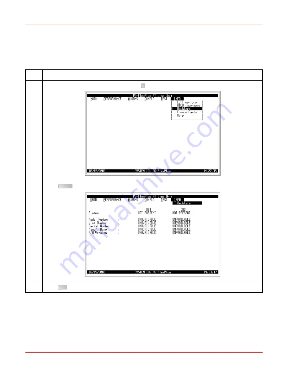
INFO — Doublers

This screen displays product identification information, manufacturing data, software and hardware revisions for 
Doublers (DB1, DB2).

Step

Action

1

At the Main Menu screen, select 

INFO

. Press   to choose 

Doublers

. The following screen appears.

2

Press 

. The following screen appears.

3

Press 

. The Main Menu screen reappears.

ENTER

ESC

Summary of Contents for PG-Flex FRL-842

Page 1: ...Section SCP FRL842 013 01H PG Flex 24 Channel Remote Terminal Line Unit Technical Practice Model List CLEI Code FRL 842 1C VAR1KH0A...

Page 2: ......

Page 3: ...ntained in this document is company private to ADC DSL Systems Inc and shall not be modified used copied reproduced or disclosed in whole or in part without the written consent of ADC Contents herein...

Page 4: ...original container Element Meaning Bold font Text that you must input exactly as shown e g type 1 for card 1 menu buttons e g ACCEPT SHELF OPTIONS or menu screen options e g ALARMS screen that you mu...

Page 5: ...842 10 Administration 11 Front Panel Craft Port to Terminal Connections 11 Navigational Methods 13 Testing Configuration and Maintenance 14 Menus and Display Structure 14 Log On Directly Through The...

Page 6: ...s 98 CONFIG Channel Unit Alarm Types 101 CONFIG POTS Options 104 CONFIG LS GS Options Integrated 107 CONFIG LS GS Options Universal 108 CONFIG Set Factory Defaults 111 CONFIG Timeslot Configuration In...

Page 7: ...April 22 2003 SCP FRL842 013 01H ADC Telecommunications Inc v Returns 137 FCC Class B Compliance 138 Modifications 138...

Page 8: ...SCP FRL842 013 01H April 22 2003 vi ADC Telecommunications Inc...

Page 9: ...Configuration 2 Figure 2 Typical Universal Configuration 2 Figure 3 FRL 842 Front Panel 6 Figure 4 Typical FRL 842 Installation 9 Figure 5 Front Panel Craft Port to Terminal Connections 11 Figure 6 T...

Page 10: ...SCP FRL842 013 01H April 22 2003 viii ADC Telecommunications Inc...

Page 11: ...u Options 69 Table 13 Systems Options Integrated 76 Table 14 Systems Options Universal 77 Table 15 Alarm Types Reported 80 Table 16 COLU Alarms Integrated 81 Table 17 COLU Alarms Universal 82 Table 18...

Page 12: ...SCP FRL842 013 01H April 22 2003 x ADC Telecommunications Inc...

Page 13: ...software on the FLL 814 L1 has been upgraded to 2 X or later If a single CO Line Unit or RT Line Unit has to be replaced the new card does not have to be reconfigured because the existing settings ar...

Page 14: ...d of either system type is housed in a RT Enclosure RT Enclosures are designed for indoor and outdoor applications and are provided with a diverse selection of mounting options These RT Enclosures sup...

Page 15: ...or determining the condition of the subscriber drop calculates the results and inserts TR 909 resistive signatures for MLT to read SUBSCRIBER DROP TESTING The FRL 842 supports subscriber drop testing...

Page 16: ...As the temperature of the cable increases the distance decreases Table 1 HDSL Distances Wire Gauge HDSL Distance 6 dB Margin 35 dB Loss 68 F Analog Drop 530 No Doubler 1 Doubler 2 Doublers 26 AWG 0 4...

Page 17: ...R 3580 Level 3 Human Safety UL 1950 for Restricted Access Emissions Radiation and Immunity GR 1089 CORE for Class B equipment HDSL Line Interface Two pair 784 kbps full duplex 2B1Q transmission format...

Page 18: ...2003 6 ADC Telecommunications Inc FRONT PANEL Figure 3 shows the FRL 842 front panel and Table 3 on page 7 describes the front panel LEDs Figure 3 FRL 842 Front Panel Retaining Latch Status LEDs RS 23...

Page 19: ...or Doubler Unit is equal to or below the provisioned threshold level Off Loop 1 margin is above the provisioned threshold level LOOP 2 SYNC Green On Loop 2 is in synchronization between the FLL 812 F...

Page 20: ...OOLS AND TEST EQUIPMENT No special tools or equipment are required to install the FRL 842 INSTALLATION ATTENTION STATIC SENSITIVE DEVICE DO NOT HANDLE ANY MATERIAL WITHOUT FIRST TAKING PROPER STATIC C...

Page 21: ...9 Install the FRL 842 Figure 4 Typical FRL 842 Installation Step Action 1 Open the retaining latches on the front of the FRL 842 2 Insert the FRL 842 into the card guides 3 Engage the retaining latch...

Page 22: ...alarm thresholds and there are no subscriber drop tests or other alarm faults in the system Therefore verify Table 4 front panel indications after the system powers up and establishes HDSL synchronize...

Page 23: ...842 The VT 100 interface allows real time updating of information displayed on the screen Through the craft interface screens system administration functions such as alarm checking and clearing confi...

Page 24: ...up the VT 100 craft port connections Table 5 Craft Port Configuration Control Setting Supported Default Software Flow Control XON XOFF Enabled Enabled Baud Rate 1200 2400 4800 9600 19200 38400 Autoba...

Page 25: ...ffect Moves to the next field No effect Cycle through the field options Moves up a menu level From the Main Menu the Logout screen is displayed Returns to Main Menu without accepting changes The banne...

Page 26: ...nal management system Integrated setup and Figure 7 on page 16 shows the menu structure of the terminal management system Universal setup In this section the RTLU refers to the FRL 842 and the COLU re...

Page 27: ...L History ISDN History CU History COLU Faults RTLU Faults System Options COLU System Alarm Types HDSL Alarm Thresholds HDSL Alarm Types ISDN Options ISDN Alarm Thresholds ISDN Alarm Types Channel Unit...

Page 28: ...m History HDSL History ISDN History CU History COLU Faults RTLU Faults System Options COLU System Alarm Types RTLU System Alarm Types HDSL Alarm Thesholds HDSL Alarm Types ISDN Options ISDN Alarm Thre...

Page 29: ...nown contact ADC Technical Support while at the terminal Technical Support will provide a temporary password based on the Access Key number displayed on the Logon screen Log On Directly Through The FR...

Page 30: ...C Telecommunications Inc 3 Type the Password then press After a successful login the system banner screen appears for a few seconds Then the FRL 842 Main Menu screen appears Log On Directly Through Th...

Page 31: ...ADC Telecommunications Inc 19 4 After 15 minutes of inactivity the following menu appears Press The Login screen reappears Repeat Step 1 Step 3 and Step 4 to log in again Log On Directly Through The F...

Page 32: ...stem Refer to Table 7 for sub menu options and descriptions parameters and valid values Table 7 Main Menu Options Sub Menu Options Sub Menu Descriptions Parameters Valid Values System Summary System s...

Page 33: ...c 21 MAIN System Summary This screen displays the status of the system Refer to Table 8 on page 24 for System Status information MAIN System Summary Step Action 1 At the Main Menu screen select MAIN P...

Page 34: ...RL842 013 01H April 22 2003 22 ADC Telecommunications Inc 2 Integrated Press The following screen appears Universal Press The following screen appears MAIN System Summary Continued Step Action ENTER E...

Page 35: ...22 2003 SCP FRL842 013 01H ADC Telecommunications Inc 23 3 To display channel status press The following screen appears 4 Press The Main Menu screen reappears MAIN System Summary Continued Step Action...

Page 36: ...ustomer direction towards NT1 as well as network direction towards LT BUSY Voice path through system is intact Line is off hook at RT with or without CO battery wired DS0AIS DS0 is not available due t...

Page 37: ...ave your VT 100 terminal unattended for any length of time log off until you are ready to resume work This prevents unauthorized persons from inadvertently changing any of your operating parameters an...

Page 38: ...SCP FRL842 013 01H April 22 2003 26 ADC Telecommunications Inc 3 Press The Login screen appears MAIN Logout Continued Step Action Y...

Page 39: ...S The Performance Menu provides access to HDSL and ISDN status if ISDN is installed and performance monitoring information Refer to Table 9 on page 28 for sub menu options and descriptions parameters...

Page 40: ...minute intervals Span HDSL 24 Hour History will be cleared Continue Y N 1 Y or N HDSL 7 Day History View the last 7 days of performance history plus the current day s accumulated performance history...

Page 41: ...e 31 for HDSL Summary information PERFORMANCE HDSL Summary Step Action 1 At the Main Menu screen select PERFORMANCE Press to choose HDSL Summary The following screen appears 2 Press The following scre...

Page 42: ...he margins press The following events occur minimum and maximum margins are set to the current margins time and date that the margins were last set are updated b To retain the existing minimum and max...

Page 43: ...op A B connection NO Indicates HDSL loops A and B are wired properly YES Indicates HDSL loops A and B are reversed HDSLA ES 24 Hr HDSLB ES 24 Hr Total number of errored seconds in the last 24 hours on...

Page 44: ...istory The following screen appears 2 Press The following screen appears In the Time field 15 minute interval information is displayed For example the time interval marked 9 45 contains the informatio...

Page 45: ...CONTINUE Y N prompt the following actions can be taken To clear the HDSL 24 Hour History press The following events occur 1 all HDSL 24 hour history 15 minute interval registers are set to zero and l...

Page 46: ...SCP FRL842 013 01H April 22 2003 34 ADC Telecommunications Inc 4 Press The Main Menu screen reappears PERFORMANCE HDSL 24 Hour History Continued Step Action ESC...

Page 47: ...e history plus the current day s accumulated performance history in 24 hour intervals The performance history data information displayed includes ES counts UAS counts and the status of the counts PERF...

Page 48: ...y and the current day performance information is cleared The status of the count is shown as ADJ Adjusted Time or date has been changed or the history cleared on the system during this interval COM Co...

Page 49: ...clear the HDSL 7 Day History press The following events occur 1 all HDSL 7 day history 24 hour interval registers are set to zero and labeled UNA 2 current interval is labeled as ADJ 3 time and date...

Page 50: ...ISDN performance data The displayed information includes ES and SES counts for the current hour the previous hour the current day and the previous day Bit Error BE counts for the current hour and prev...

Page 51: ...The following screen appears To view the ISDN performance data select the ISDN channel then press Universal Press The following screen appears To view the ISDN performance data select the ISDN channel...

Page 52: ...E CLEARED CONTINUE Y N prompt The following event occurs all ISDN PM counts are set to zero c To retain the existing ISDN performance data press If there are alarms associated with the performance cou...

Page 53: ...CE ISDN 7 Hour History This screen allows you to select an ISDN channel and view the ISDN 7 Hour ES history information PERFORMANCE ISDN 7 Hour History Step Action 1 At the Main Menu screen select PER...

Page 54: ...ollowing screen appears To view ISDN 7 Hour ES history select an ISDN channel unit then press Universal Press The following screen appears To view ISDN 7 Hour ES history select an ISDN channel unit th...

Page 55: ...ompt The following event occurs all ISDN PM counts are set to zero c To retain the existing performance data press If there are alarms associated with the performance counts those alarms are reset whe...

Page 56: ...ARM MENU OPTIONS The Alarm Menu provides access to the alarm status and system related alarm events Refer to Table 11 on page 45 for sub menu options and descriptions parameters and valid values ISDN...

Page 57: ...cleared Continue Y N Y or N RTLU System History View the RTLU alarm history System Alarm History will be cleared Continue Y N Y or N HDSL History View the HDSL history Span HDSL Alarm History will be...

Page 58: ...Action 1 At the Main Menu screen select ALARMS Press to choose Alarms Summary The following screen appears The alarm information displayed indicates Alarm Types CRITICAL Critical alarm is present MAJ...

Page 59: ...ons can be taken a To clear the history of all alarms select the CLEAR ALL ALARM HISTORIES button then press From the HDSL ALARM HISTORIES WILL BE CLEARED CONTINUE Y N prompt the following actions can...

Page 60: ...SCP FRL842 013 01H April 22 2003 48 ADC Telecommunications Inc 4 Press The Main Menu screen reappears ALARMS Alarms Summary Continued Step Action ESC...

Page 61: ...sioned alarm type and the current status ALARMS COLU System History Integrated Step Action 1 At the Main Menu screen select ALARMS Press to choose COLU System History The following screen appears 2 Pr...

Page 62: ...RY button then press From the SYSTEM ALARM HISTORY WILL BE CLEARED CONTINUE Y N prompt the following actions can be taken To clear the COLU alarm history press The following events occur 1 COLU alarm...

Page 63: ...April 22 2003 SCP FRL842 013 01H ADC Telecommunications Inc 51 4 Press The Main Menu screen reappears ALARMS COLU System History Integrated Continued Step Action ESC...

Page 64: ...sioned alarm type and the current status ALARMS COLU System History Universal Step Action 1 At the Main Menu screen select ALARMS Press to choose COLU System History The following screen appears 2 Pre...

Page 65: ...ORY button then press From the SYSTEM ALARM HISTORY WILL BE CLEARED CONTINUE Y N prompt the following actions can be taken To clear the COLU alarm history press The following events occur 1 COLU alarm...

Page 66: ...SCP FRL842 013 01H April 22 2003 54 ADC Telecommunications Inc 4 Press The Main Menu screen reappears ALARMS COLU System History Universal Continued Step Action ESC...

Page 67: ...ned alarm type and the current status ALARMS RTLU System History Step Action 1 At the Main Menu screen select ALARMS Press to choose RTLU System History The following screen appears 2 Press The follow...

Page 68: ...HISTORY button then press From the SYSTEM ALARM HISTORY WILL BE CLEARED CONTINUE Y N prompt the following actions can be taken To clear the RTLU alarm history press The following events occur 1 RTLU...

Page 69: ...April 22 2003 SCP FRL842 013 01H ADC Telecommunications Inc 57 4 Press The Main Menu screen reappears ALARMS RTLU System History Continued Step Action ESC...

Page 70: ...rence the provisioned alarm type and the current status ALARMS HDSL History Step Action 1 At the Main Menu screen select ALARMS Press to choose HDSL History The following screen appears 2 Press The fo...

Page 71: ...HDSL alarm history select the CLEAR ALL HDSL ALARM HISTORY button then press From the HDSL ALARM HISTORY WILL BE CLEARED CONTINUE Y N prompt the following actions can be taken To clear the HDSL alarm...

Page 72: ...Information includes the provisionable alarm type the current status of the alarm the number of times the alarm was reported the date and time of the first and last occurrence and the current status A...

Page 73: ...ated Press The following screen appears To view the ISDN History select the ISDN channel then press Universal Press The following screen appears To view the ISDN History select the ISDN channel then p...

Page 74: ...ISDN channel then press The following screen appears The status OK displays in the Current column when the alarm is not present The status Active displays when an alarm is present A description of th...

Page 75: ...ILL BE CLEARED CONTINUE Y N prompt the following actions can be taken To clear the ISDN alarm history press The following events occur 1 all ISDN alarm history counts are set to zero 2 time and date t...

Page 76: ...SCP FRL842 013 01H April 22 2003 64 ADC Telecommunications Inc 5 Press The Main Menu screen reappears ALARMS ISDN History Continued Step Action ESC...

Page 77: ...f the first and last occurrence and the current status ALARMS CU History Step Action 1 At the Main Menu screen select ALARMS Press to choose CU History The following screen appears 2 Press The followi...

Page 78: ...s can be taken To clear the CU alarm history press The following events occur 1 all CU alarm history counts are set to zero 2 time and date that the registers were last cleared are updated Clearing th...

Page 79: ...on 1 At the Main Menu screen select ALARMS Press to choose COLU Faults The following screen appears 2 Press The following screen appears If there are no faults detected then the COLU Faults screen dis...

Page 80: ...ion 1 At the Main Menu screen select ALARMS Press to choose RTLU Faults The following screen appears 2 Press The following screen appears If there are no faults detected then the RT Faults screen disp...

Page 81: ...G Menu Option Timeslot Configuration menu option is present in an Integrated setup and Channel Configuration menu option is present in an Universal setup The Integrated setup is shown below IMPORTANT...

Page 82: ...Thresholds See Table 19 on page 88 for HDSL Alarm Thresholds Provision HDSL alarm thresholds HDSL Alarm Thresholds will be Changed Continue Y N Y or N HDSL Alarm Types See Table 20 on page 91 for HDS...

Page 83: ...tinue Y N Y or N POTS Options See Table 25 on page 106 for POTS Options Provision the ringing frequency for POTS lines POTS Options will be Changed Continue Y N Y or N LS GS Options View the Loop Star...

Page 84: ...nnel and channel unit Timeslot Configuration will be Changed Continue Y N Y or N Channel Configuration Universal setup Allows each individual channel to be set as enabled or disabled Channel Configura...

Page 85: ...sioning of system options such as Subscriber Test Response Mode and System ID Refer to Table 13 on page 76 for System Options Integrated and Table 14 on page 77 for System Options Universal CONFIG Sys...

Page 86: ...L842 013 01H April 22 2003 74 ADC Telecommunications Inc 2 Integrated Press The following screen appears Universal Press The following screen appears CONFIG System Options Continued Step Action ENTER...

Page 87: ...ons select the ACCEPT SYSTEM OPTION CHANGES button then press From the SHELF OPTIONS WILL BE CHANGED CONTINUE Y N prompt the following actions can be taken To save the shelf options press The followin...

Page 88: ...lus System ID 24 chars max 24 Alphanumeric Characters maximum Configurable identification string for the system can be up to 24 characters The System ID is always visible at the bottom of every screen...

Page 89: ...r changing the System ID Any printable characters including spaces are valid PG Flex RT Auto Logout DISABLED Auto logout feature is disabled DISABLED 5 Screens session logs out after 5 minutes of inac...

Page 90: ...age 81 shows the COLU system alarms Integrated setup and Table 17 on page 82 shows the COLU system alarms Universal setup Table 15 on page 80 provides a description of the Alarm types reported CONFIG...

Page 91: ...mation select the GO TO RTLU ALARMS button then press d To save the COLU alarm type changes select the ACCEPT SYSTEM ALARM TYPE CHANGES button then press From the SYSTEM ALARM TYPE CHANGES WILL BE CHA...

Page 92: ...munications Inc Table 15 Alarm Types Reported Settings Reported Alarm LED Lit Main Shelf Summary History Updated CR Critical Yes Yes Yes Yes MJ Major Yes Yes Yes Yes MN Minor Yes Yes Yes Yes NA Not Al...

Page 93: ...HDSL payload is out of synchronization MJ NO RTLU S W CR MJ MN NA NR RTLU has no application software and is awaiting software download MJ LOW TEMPERATURE CR MJ MN NA NR Temperature at RTLU is too lo...

Page 94: ...NA NR Ground fault detected on HDSL loop MJ HDSL PAYLOAD SYNC CR MJ MN NA NR HDSL payload is out of synchronization MJ NO RTLU S W CR MJ MN NA NR RTLU has no application software and is awaiting soft...

Page 95: ...alarms Table 18 on page 85 shows the RTLU system alarm fields values descriptions and default settings Table 15 on page 80 provides a description of the Alarm types reported CONFIG RTLU System Alarm T...

Page 96: ...ation select the GO TO COLU ALARMS button then press d To save the RTLU alarm type changes select the ACCEPT SYSTEM ALARM TYPE CHANGES button then press From the SYSTEM ALARM TYPE CHANGES WILL BE CHAN...

Page 97: ...ure at RTLU MJ LOW TEMPERATURE CR MJ MN NA NR Temperature at RTLU is too low MN HIGH TEMPERATURE CR MJ MN NA NR Temperature at RTLU is too high MJ COLU RTLU MISMATCH CR MJ MN NA NR COLU RTLU mismatch...

Page 98: ...ues for the 15 minute and 24 hour ES and UAS counts and HDSL margin Table 19 on page 88 shows the HDSL Alarm Threshold fields values descriptions and default settings CONFIG HDSL Alarm Thresholds Step...

Page 99: ...L Alarm Threshold changes select the ACCEPT HDSL ALARM THRESHOLD CHANGES button then press From the HDSL ALARM THRESHOLDS WILL BE CHANGED CONTINUE Y N prompt the following actions can be taken To save...

Page 100: ...HDSL ES 24 hour alarm is generated if ES 24 hour counts become equal to or greater than this threshold 170 HDSL UAS 15 MIN 0 to 900 HDSL UAS 15 minutes alarm is generated in the current 15 minute HDS...

Page 101: ...ng of the alarm types for all HDSL alarms Table 20 on page 91 lists the HDSL Alarm Type fields values descriptions and default settings CONFIG HDSL Alarm Types Step Action 1 At the Main Menu screen se...

Page 102: ...changes select the ACCEPT HDSL ALARM TYPE CHANGES button then press From the HDSL ALARM TYPES WILL BE CHANGED CONTINUE Y N prompt the following actions can be taken To save the HDSL Alarm Types change...

Page 103: ...eaches or exceeds this threshold MN HDSL UAS 15 MN CR MJ MN NA NR HDSL UAS 15 minute alarm is generated if the current 15 minute HDSL UAS count reaches or exceeds this threshold MN HDSL UAS 24 HR CR M...

Page 104: ...able 21 on page 94 lists the ISDN Option fields values descriptions and default settings CONFIG ISDN Options Step Action 1 At the Main Menu screen select CONFIG Press to choose ISDN Options The follow...

Page 105: ...N Option changes select the ACCEPT ISDN OPTION CHANGES button then press From the ISDN OPTIONS WILL BE CHANGED CONTINUE Y N prompt the following actions can be taken To save the ISDN Option changes pr...

Page 106: ...ntire transport path INTERIM PATH SEGMENTED PATH Considers the channel as separate sections and individually collects error rates for each DSL loop B Channel Swap NORMAL Channels B1 and B2 at the CO I...

Page 107: ...ed hourly and daily Table 22 on page 97 lists the ISDN Alarm Threshold fields values descriptions and default settings CONFIG ISDN Alarm Thresholds Step Action 1 At the Main Menu screen select CONFIG...

Page 108: ...he ISDN Alarm Threshold changes select the ACCEPT ISDN THRESHOLD CHANGES button then press From the ISDN THRESHOLDS WILL BE CHANGED CONTINUE Y N prompt the following actions can be taken To save the I...

Page 109: ...s this threshold 40 DAILY ES 1 to 4095 ISDN daily ES alarm is generated if the accumulated daily ES count at the COLU RTLU reaches or exceeds this threshold 100 HOURLY SES 1 to 127 ISDN hourly SES ala...

Page 110: ...le 23 on page 100 lists the ISDN Alarm Type fields values descriptions and default settings CONFIG ISDN Alarm Types Step Action 1 At the Main Menu screen select CONFIG Press to choose ISDN Alarm Types...

Page 111: ...changes select the ACCEPT ISDN ALARM TYPE CHANGES button then press From the ISDN ALARM TYPES WILL BE CHANGED CONTINUE Y N prompt the following actions can be taken To save the ISDN Alarm Type change...

Page 112: ...RTLU reaches or exceeds its threshold value A single threshold value is used for threshold errors in the customer or network direction MN HOURLY SES CR MJ MN NA NR Generated if the accumulated hourly...

Page 113: ...the subscriber s equipment no longer rings When an RT channel unit detects the failure of one of these circuits it generates an alarm of the severity selected on this screen Table 24 on page 103 lists...

Page 114: ...T CHANNEL UNIT ALARM TYPE CHANGES button then press From the CHANNEL UNIT ALARM TYPES WILL BE CHANGED CONTINUE Y N prompt the following actions can be taken To save the Channel Unit Alarm Type changes...

Page 115: ...y MN RTCU 2 RING BUFFER FAILURE CR MJ MN NA NR RTLU has detected a ring buffer failure on RTCU2 Associated CU must be replaced to restore ringing functionality MN RTCU 3 RING BUFFER FAILURE CR MJ MN N...

Page 116: ...llows provisioning of POTS lines Table 25 on page 106 lists the POTS Option fields values descriptions and default settings CONFIG POTS Options Step Action 1 At the Main Menu screen select CONFIG Pres...

Page 117: ...sired value c To save the POTS Option changes select the ACCEPT POTS OPTION CHANGES button then press From the POTS OPTIONS WILL BE CHANGED CONTINUE Y N prompt the following actions can be taken To sa...

Page 118: ...g generator frequency for all POTS circuits served by the COLU or 3 RTLUs 20 HZ Local Loop Length SHORT All POTS circuits support short subscriber drops and results in slightly reduced power consumpti...

Page 119: ...tart configuration Integrated setup CONFIG LS GS Options Integrated Step Action 1 At the Main Menu screen select CONFIG Press to choose LS GS Options The following screen appears 2 Press The following...

Page 120: ...oop Start and Ground Start configuration Universal setup CONFIG LS GS Options Universal Step Action 1 At the Main Menu screen select CONFIG Press to choose LS GS Options The following screen appears 2...

Page 121: ...t the SAVE SETTINGS button then press From the GROUND LOOP SETTINGS WILL BE CHANGED CONTINUE Y N prompt the following actions can be taken To save the LS GS Option changes press The following events o...

Page 122: ...2003 110 ADC Telecommunications Inc 4 To view the Help Screen select the HELP SCREEN button then press The Help Screen appears 5 Press The Main Menu screen reappears CONFIG LS GS Options Universal Con...

Page 123: ...onfiguration data back to the original factory default setting CONFIG Set Factory Defaults Step Action 1 At the Main Menu screen select CONFIG Press to choose Set Factory Defaults The following screen...

Page 124: ...N DATA WILL BE SET TO FACTORY DEFAULTS THIS MAY BE SERVICE AFFECTING CONTINUE Y N prompt the following actions can be taken To save the Factory Default changes press The following events occur all cur...

Page 125: ...quire three timeslots per circuit When the system initially powers up the Timeslot Configuration screen displays POTG8 channel units installed in CU1 CU2 and CU3 regardless of what channel units are a...

Page 126: ...SCP FRL842 013 01H April 22 2003 114 ADC Telecommunications Inc 2 Press The following screen appears CONFIG Timeslot Configuration Integrated Continued Step Action ENTER...

Page 127: ...To assign the SUB CH value press to toggle to the desired value or press or to move to next option e To save the Timeslot Configuration changes select the SAVE SETTINGS button then press From the TIME...

Page 128: ...TS loop start and ground start POTS8 ISDN4 4 channel unit for ISDN POTS8 EMPTY Current not configured or timeslot is empty EMPTY CU 1 Possible channel unit values Channel unit 4 value is only supporte...

Page 129: ...abled or disabled Universal setup If any one card COLU RTLU COCU or RTCU is removed replaced or reinserted the channel configuration is automatically preserved CONFIG Channel Configuration Universal S...

Page 130: ...Channels select the DISABLE ALL CHANNELS button then press d To save the Channel Configuration changes select the SAVE SETTINGS button then press From the CHANNEL CONFIGURATION WILL BE CHANGED CONTINU...

Page 131: ...01H ADC Telecommunications Inc 119 4 To view the Help Screen select the HELP button then press The Help screen appears 5 Press The Main Menu screen reappears CONFIG Channel Configuration Universal Con...

Page 132: ...ns If you attempting to run a second test when one test is already in progress a flashing warning message appears Wait a few minutes then try to run the test again Sub Menu Options Sub Menu Descriptio...

Page 133: ...articular channel CAUTION Performing a subscriber drop test on any channel interrupts service on the line under test The remaining lines on the system remain in service TEST Subscriber Drop Test Step...

Page 134: ...toggle to the desired value c To accept the changes select the Accept CU Channel and Start Test button then press d From the ISDN CU CH CHOSEN FOR TEST WARNING CALLS IN PROGRESS ON TEST CIRCUIT WILL...

Page 135: ...ubscriber Test Failure Condition and Test Status results is displayed Tests are performed in the order of display If a test fails the remaining tests are not performed as per TA 909 It takes approxima...

Page 136: ...ation manufacturing data software and hardware revisions for COLU and RTLU COCU Inventory Universal setup Displays product identification information manufacturing data software and hardware revisions...

Page 137: ...ys product identification information manufacturing data software and hardware revisions for COLU and RTLU Step Action 1 At the Main Menu screen select INFO Press to choose LU Inventory The following...

Page 138: ...tification information manufacturing data software versions and hardware revisions for CO Channel Units CU1 CU2 CU3 Universal setup Step Action 1 At the Main Menu screen select INFO Press to choose CO...

Page 139: ...identification information manufacturing data software and hardware revisions for RT Channel Units CU1 CU2 CU3 CU4 Step Action 1 At the Main Menu screen select INFO Press to choose RTCU Inventory The...

Page 140: ...product identification information manufacturing data software and hardware revisions for Doublers DB1 DB2 Step Action 1 At the Main Menu screen select INFO Press to choose Doublers The following scr...

Page 141: ...t identification information manufacturing data software and hardware revisions for Common Cards PMU and PMX cards Step Action 1 At the Main Menu screen select INFO Press to choose Common Cards The fo...

Page 142: ...NFO Help This screen provides information on using the system screens and menus Step Action 1 At the Main Menu screen select INFO Press to choose Help The following screen appears 2 Press The followin...

Page 143: ...LL 814 If power is not present at COT Shelf backplane replace the CO fuse FRL 842 power supply has failed Replace the FRL 842 FLL 812 FLL 814 power supply has failed Replace the FLL 812 FLL 814 LOOP 1...

Page 144: ...MX 744 s in integrated mode only PMX 744 Verify the system options are set correctly FLL 814 Verify the system options are set correctly Problem with the DS1 signals in integrated mode only DS1 Verify...

Page 145: ...eature L1A L1 L1A L1B L2 L1 L1A L1B L1C L2 Power Line Local Alarms System Environmental Fan Subscriber Drop Testing TR 909 Bypass Pair Management TL1 Switch Interface UDLC IDLC Services POTS ISDN Cust...

Page 146: ...App S W Version FLL 812 L1A 1 x Compatible with FRL 842 L1B L1C L2 3 2 or later FLL 814 L1 1 1 Compatible with FRL 842 L1 1 1 FLL 814 L1A L2 2 x Compatible with FRL 842 L1A 2 X FLL 814 L1B 3 2 Compat...

Page 147: ...al Office COT Central Office Terminal CPE Customer Premises Equipment CU Channel Unit D DCE Data Carrier Equipment DS0 Digital Signal Level 0 DS1 Digital Signal Level 1 DSL Digital Subscriber Line DSR...

Page 148: ...lding System NT1 Network Termination Type 1 P PCM Pulse Code Modulation PGTC Pair Gain Test Controller PM Performance Monitoring PBX Private Branch Exchange POTS Plain Old Telephone Service PPM Parts...

Page 149: ...ted below Telephone 800 366 3891 Email Address rma ADC com 3 Include the following information in writing along with the equipment you are returning Company name and address Contact name and telephone...

Page 150: ...rantee that interference will not occur in a particular installation If this equipment does cause harmful interference to radio or television reception which can be determined by turning the equipment...

Page 151: ......

Page 152: ...World Headquarters ADC Telecommunications Inc 12501 Whitewater Drive Minnetonka Minnesota USA 55343 For Technical Assistance 800 366 3891 Zy 7x 1258897...

Reviews: