Overview
LTPH-UG-1166-01
2
July 15, 2002
HMS-317 and HMS-318
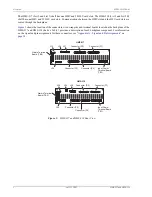
The HMS-317 (List 2 and List 3) shelf has one HMU and 28 HLU card slots. The HMS-318 (List 2 and List 2B)
shelf has one HMU and 22 HLU card slots. Communications between the HMU slot and the HLU card slots are
routed through the backplane.
shows the location of the connectors, wire-wrap pins and terminal boards located on the backplane of the
provides a description of each backplane component. For information
on the signal and pin assignments for these connectors, see
“Appendix A - Signal and Pin Assignments” on
.
Figure 2.
HMS-317 and HMS-318 Rear View
TB2
TB2
HMS-317
HMS-318
J32
J34
J31
Connector (P1)
Connector (P2)
Connector (P4)
Connector (P3)
J30
Input Power
Terminal Board
(TB1)
Alarms Terminal
Board (TB2)
J26
J34
J25
Connector (P1)
Connector (P2)
Alarms Terminal
Board (TB2)
Connector (P4)
Connector (P3)
Input Power
Terminal Board
(TB1)
J24
AUX Rs232 PORT
XMT FROM DSX
RCV TO DSX
HDSL LOOP 1 (XMT TO SPAN)
HDSL LOOP 2 (RCV FROM SPAN)
OS Rs232 PORT
XMT FROM DSX
RCV TO DSX
HDSL LOOP 1 (XMT TO SPAN)
HDSL LOOP 2 (RCV FROM SPAN)
OS Rs232 PORT


