background image

Appendix A - Signal and Pin Assignments


 LTPH-UG-1166-01

18

July 15, 2002

 HMS-317 and HMS-318

A

PPENDIX

 A - S

IGNAL


AND

 P

IN

 A

SSIGNMENTS

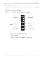
This section provides information on Tip and Ring signal and pin assignments to HMS-317 and HMS-318 
management shelves.

P1-DSX Receive, Tip and Ring

........................................................................................

18

P2-DSX Transmit, Tip and Ring

......................................................................................

20

P3-HDSL Loop 1, Tip and Ring

.......................................................................................

22

P4-HDSL Loop 2, Tip and Ring

.......................................................................................

24

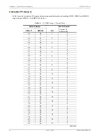
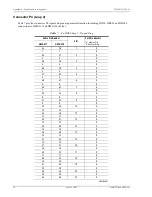
Connector P1 - DSX Receive

Table 4

 provides signal and pin assignment information for making DSX receive circuit connections to HMS-317 

and HMS-318 shelves.

Table 4.

P1-DSX Receive, Tip and Ring

Cable Pin Number

Slot

Card Slot Pin Number

“B” denotes Tip
“2” denotes Ring

HMS-317

HMS-318

33

26

1

B

1

1

2

34

27

2

B

2

2

2

35

28

3

B

3

3

2

36

29

4

B

4

4

2

37

30

5

B

5

5

2

38

31

6

B

6

6

2

39

32

7

B

7

7

2

40

33

8

B

8

8

2

41

34

9

B

9

9

2

42

35

10

B

10

10

2

43

36

11

B

11

11

2

44

37

12

B

12

12

2

45

38

13

B

13

13

2

46

39

14

B

14

14

2

47

40

15

B

Continued

Summary of Contents for HiGain HMS-317 List 2

Page 1: ...Model List Part Number CLEI HMS 317 List 2 150 1128 02 T1MFUR04 HMS 317 List 3 150 1128 03 T1MF1R04 HMS 318 List 2 150 1129 02 T1MFVS04 HMS 318 List 2B 150 1129 22 N A HMS 317 AND HMS 318 MANAGEMENT SHELF HMS 317 HMS 318 ...

Page 2: ...tification purposes only and may be trademarks or registered trademarks of their respective companies Disclaimer of Liability Information contained in this document is company private to ADC DSL Systems Inc and shall not be modified used copied reproduced or disclosed in whole or in part without the written consent of ADC Contents herein are current as of the date of publication ADC reserves the r...

Page 3: ...extent of damage to the transportation company and to ADC DSL Systems Inc Order replacement equipment if necessary Check the packing list to ensure complete and accurate shipment of each listed item If the shipment is short or irregular contact ADC DSL Systems Inc as described in Appendix D Product Support on page 28 If you must store the equipment for a prolonged period store the equipment in its...

Page 4: ...Unpack and Inspect Your Shipment LTPH UG 1166 01 iv July 15 2002 HMS 317 and HMS 318 ...

Page 5: ...Connections 10 Asynchronous Management Ports 13 Multishelf Network Connections 14 Power Dissipation Factors 15 Installation__________________________________________________________________________ 16 Site Requirements 16 Shelf Installation 16 Appendix A Signal and Pin Assignments________________________________________________ 18 Connector P1 DSX Receive 18 Connector P2 DSX Transmit 20 Connector ...

Page 6: ...LU Slot Wire wrap Pinouts for HDSL4 Circuits 8 8 ADC HCP 322 List 1 and List 2 Connector Panel 9 9 Typical HiGain G 703 Application 9 10 HLU Slot Wire wrap Pinouts for G 703 HDSL Circuits 10 11 HLU Slot Wire wrap Pinouts for G 703 HDSL2 Circuits 11 12 HLU Slot Wire wrap Pinouts for G 703 HDSL4 Circuits 12 13 HMS OS and AUX Asynchronous Management Ports 13 14 Multishelf Network Ports 14 15 Central ...

Page 7: ...IST OF TABLES 1 HMS Backplane Connections 3 2 J30 J24 OS RS 232 PORT DTE 13 3 J31 J25 AUX RS 232 PORT DTE 14 4 P1 DSX Receive Tip and Ring 18 5 P2 DSX Transmit Tip and Ring 20 6 P3 HDSL Loop 1 Tip and Ring 22 7 P4 HDSL Loop 2 Tip and Ring 24 8 Standard PIC Color Code 26 ...

Page 8: ...List of Tables LTPH UG 1166 01 x July 15 2002 HMS 317 and HMS 318 ...

Page 9: ...shelf supports DSX 1 interfaces at the central office CO and the remote end with remote provisioning and performance monitoring In addition the HMS 318 supports G 703 circuit connections HMS 317 and HMS 318 shelves are shipped with Adjustable mounting brackets that allow the shelf to be positioned in the equipment rack to match the recess of existing equipment M5 x 0 8 by 10 mm mounting screws 4 B...

Page 10: ...ption of each backplane component For information on the signal and pin assignments for these connectors see Appendix A Signal and Pin Assignments on page 18 Figure 2 HMS 317 and HMS 318 Rear View TB2 TB2 HMS 317 HMS 318 J32 J34 J31 Connector P1 Connector P2 Connector P4 Connector P3 J30 Input Power Terminal Board TB1 Alarms Terminal Board TB2 J26 J34 J25 Connector P1 Connector P2 Alarms Terminal ...

Page 11: ...rs P1 and P2 for DSX 1 receive and transmit connections and two 50 pin Amphenol type male connectors P3 and P4 on the backplane These connectors provide HDSL Span Loop1 and Loop 2 receive and transmit connections to the shelf These connectors provide Tip and Ring connections for all cards in the shelf Use a mating 50 pin AMP Style Kit No 2 22913 1 connector for 24 26 AWG cables Table 1 HMS Backpla...

Page 12: ...st power failure in the event that one power supply is lost This feature requires the 2 ground terminals to be tied together on the HMU card HMS 317 List 3 Input Power Connections The HMS 317 List 3 requires two battery supply sources 48VA bus and 48VB bus The power and fan inputs terminal block TB1 see Figure 3 provides a central connection point for the CO primary and redundant input power feeds...

Page 13: ...ovides a central connection point to the Normally Closed NC Common COM and Normally Open NO relay contacts for installing optional alarm inputs connections Figure 4 Alarms Terminal Block TB2 NC C NO NC C NO NC C NO NC C NO NC C NO NC C NO NC C NO CRIT AUD CRIT VIS MAJ AUD MAJ VIS MIN AUD MIN VIS SYS ID ACO 1 2 3 4 5 6 7 8 9 10 11 12 13 14 15 16 17 18 19 20 21 22 ...

Page 14: ...dividual card connectors through the HMS backplane wire wrap pins 0 045 inch square 1 14 mm Straps for cable dressings and a protective Lexan rear cover are provided with the shelf Figure 5 shows the HLU card slot pinouts on the HMS backplane Figure 5 HLU Slot Wire wrap Pinouts for HDSL Circuits DS1 Transmit Tip DS1 Ring Transmit DS1 Receive Tip DS1 Ring Receive A B C D E F J H Error Alarm Bus Gro...

Page 15: ... 3 HDSL2 Wire wrap Connections DSX 1 and HDSL2 connections can be made to the individual card connectors through the HMS backplane wire wrap pins 0 045 inch square 1 14 mm Straps for cable dressings and a protective Lexan rear cover are provided with the shelf Figure 6 shows the HLU card slot pinouts on the HMS backplane Figure 6 HLU Slot Wire wrap Pinouts for HDSL2 Circuits DSX 1 IN Tip DSX 1 Tip...

Page 16: ...ap Connections DSX 1 and HDSL2 connections can be made to the individual card connectors through backplane wire wrap pins 0 045 inch square 1 14 mm Straps for cable dressings and a protective Lexan rear cover are provided with the shelf Figure 7 shows the HLU card slot pinouts on the HMS backplane Figure 7 HLU Slot Wire wrap Pinouts for HDSL4 Circuits DSX 1 IN Tip DSX 1 Tip 1 OUT A B C D E F J H G...

Page 17: ...its housed in the HMS 318 shelf The ADC HCP 322 List 1 panel has 44 BNC connectors for connecting G 703 75W circuits to ELU 319 List 1 List 5 and 5D line units The ADC HCP 322 List 2 panel contains 22 DB 15 connectors for connecting G 703 120W circuits to ELU 319 List 6 and 6D line units The ADC HCP 322 List 2 panel also includes wire wrap pins for optionally connecting the connector case of each ...

Page 18: ... circuits Figure 10 HLU Slot Wire wrap Pinouts for G 703 HDSL Circuits G 703 Transmit Tip G 703 Ring Transmit G 703 Receive Tip G 703 Ring Receive A B C D E F J H Error Alarm Bus Ground GND HDSL Loop 1 Tip HDSL Loop 1 Receive Minor Alarm Loss Of Signal Alarm LOS ALM Management Bus Frame Ground 48 Vdc Battery HDSL Loop 2 Transmit HDSL Loop 2 Receive FL not used Fuse Alarm 1 2 3 4 5 6 7 8 9 10 K L F...

Page 19: ...e wrap Pinouts for G 703 HDSL2 Circuits G 703 IN Tip G 703 Tip 1 OUT A B C D E F J H Ground GND HDSL2 Span Tip HDSL2 Span Ring System Alarm Management Bus Frame Ground 48 Vdc Battery Factory use only Fuse Alarm 1 2 3 4 5 6 7 8 9 10 K L Fuse alarm normally floating 0 to 80 Vdc maximum and at 48Vdc 10 ma maximum when activated System alarm and management bus reserved Notes G 703 IN Ring G 703 Ring 1...

Page 20: ...G 703 HDSL4 Circuits G 703 Tip IN G 703 Tip 1 OUT A B C D E F J H Ground GND HDSL4 Loop 1 Tip HDSL4 Loop 1 Ring System Alarm Management Bus Frame Ground 48 Vdc Battery Factory use only Fuse Alarm 1 2 3 4 5 6 7 8 9 10 K L Fuse alarm normally floating 0 to 80 Vdc maximum and at 48Vdc 10 ma maximum when activated System alarm and management bus reserved Notes G 703 Ring IN G 703 Ring 1 OUT HDSL4 Loop...

Page 21: ... the OS communication port connector Table 3 on page 14 lists the pin connections for the AUX communication port connector Figure 13 HMS OS and AUX Asynchronous Management Ports The HMU 319 requires that DSR be asserted by the connected DCE in order to establish communications on this port The HMU 319 always asserts DTR on this port Table 2 J30 J24 OS RS 232 PORT DTE Pin No Signal Direction 2 Tran...

Page 22: ...802 3 Ethernet LAN The backplane RJ 45 connector J34 provides a 10BASE 2 and a 10BASE T IEEE 802 3 Ethernet LAN For detailed signal and pin assignment information on the BNC and RJ 45 connectors see Appendix A Signal and Pin Assignments on page 18 Figure 14 Multishelf Network Ports Table 3 J31 J25 AUX RS 232 PORT DTE Pin No Signal Direction 2 Transmit Data TD Out 3 Receive Data RD In 6 Data Set Re...

Page 23: ...trates heat baffles should be placed between every two shelves to help reduce the chimney heating effect The maximum allowable power dissipation for each equipment rack is 800 watts for a 19 inch wide rack 946 watts for a 23 inch wide rack Figure 15 Central Office Equipment Rack Configuration Refer to the HLU 319 or ELU 319 user manual to determine the maximum number of HLU cards that can be insta...

Page 24: ...nal fan inputs to TB1 Figure 16 When mounting a 19 inch HMS 318 shelf into a 23 inch equipment rack position the shorter side of the bracket against the shelf See Figure 2 on page 2 for the location of the HDSL Span connectors HDSL Span pin assignments are listed in Appendix A Signal and Pin Assignments on page 18 Standard PIC cable color codes are listed in Table 8 on page 26 The HCP 322 connecto...

Page 25: ... to the RS 232 ports connect the shelf ground pins and the terminal ground bus to the TB1 FG pin The FAN terminals on TB1 provide access to the Normally Open NO Form A fan relay contact located on the HMU 319 management unit A temperature monitor activates this fan relay when the shelf temperature exceeds 45 C 1 C and deactivates the relay when the temperature drops below 35 C 1 C If the temperatu...

Page 26: ...2 Tip and Ring 24 Connector P1 DSX Receive Table 4 provides signal and pin assignment information for making DSX receive circuit connections to HMS 317 and HMS 318 shelves Table 4 P1 DSX Receive Tip and Ring Cable Pin Number Slot Card Slot Pin Number B denotes Tip 2 denotes Ring HMS 317 HMS 318 33 26 1 B 1 1 2 34 27 2 B 2 2 2 35 28 3 B 3 3 2 36 29 4 B 4 4 2 37 30 5 B 5 5 2 38 31 6 B 6 6 2 39 32 7 ...

Page 27: ...9 42 17 B 17 17 2 50 43 18 B 18 18 2 51 44 19 B 19 19 2 52 45 20 B 20 20 2 53 46 21 B 21 21 2 54 47 22 B 22 22 2 55 23 B 23 2 56 24 B 24 2 57 25 B 25 2 58 26 B 26 2 59 27 B 27 2 60 28 B 28 2 Table 4 P1 DSX Receive Tip and Ring Cont Cable Pin Number Slot Card Slot Pin Number B denotes Tip 2 denotes Ring HMS 317 HMS 318 ...

Page 28: ...ansmit Tip and Ring Cable Pin Number Slot Card Pin Number A denotes Tip 1 denotes Ring HMS 317 HMS 318 33 26 1 A 1 1 1 34 27 2 A 2 2 1 35 28 3 A 3 3 1 36 29 4 A 4 4 1 37 30 5 A 5 5 1 38 31 6 A 6 6 1 39 32 7 A 7 7 1 40 33 8 A 8 8 1 41 34 9 A 9 9 1 42 35 10 A 10 10 1 43 36 11 A 11 11 1 44 37 12 A 12 12 1 45 38 13 A 13 13 1 46 39 14 A 14 14 1 47 40 15 A 15 15 1 47 41 16 A 16 16 1 49 42 17 A 17 17 1 5...

Page 29: ...17 and HMS 318 July 15 2002 21 21 21 1 54 47 22 A 22 22 1 55 23 A 23 1 56 24 A 24 1 57 25 A 25 1 58 26 A 26 1 59 27 A 27 1 60 28 A 28 1 Table 5 P2 DSX Transmit Tip and Ring Cont Cable Pin Number Slot Card Pin Number A denotes Tip 1 denotes Ring HMS 317 HMS 318 ...

Page 30: ...p 1 Tip and Ring Cable Pin Number Card Pin Number HMS 317 HMS 318 Slot F denotes Tip 6 denotes Ring 33 26 1 F 1 1 6 34 27 2 F 2 2 6 35 28 3 F 3 3 6 36 29 4 F 4 4 6 37 30 5 F 5 5 6 38 31 6 F 6 6 6 39 32 7 F 7 7 6 40 33 8 F 8 8 6 41 34 9 F 9 9 6 42 35 10 F 10 10 6 43 36 11 F 11 11 6 44 37 12 F 12 12 6 45 38 13 F 13 13 6 46 39 14 F 14 14 6 47 40 15 F 15 15 6 47 41 16 F 16 16 6 49 42 17 F 17 17 6 50 4...

Page 31: ...317 and HMS 318 July 15 2002 23 21 21 6 54 47 22 F 22 22 6 55 23 F 23 6 56 24 F 24 6 57 25 F 25 6 58 26 F 26 6 59 27 F 27 6 60 28 F 28 6 Table 6 P3 HDSL Loop 1 Tip and Ring Cont Cable Pin Number Card Pin Number HMS 317 HMS 318 Slot F denotes Tip 6 denotes Ring ...

Page 32: ...p 2 Tip and Ring Cable Pin Number Slot Card Pin Number K denotes Tip 9 denotes Ring HMS 317 HMS 318 33 26 1 K 1 1 9 34 27 2 K 2 2 9 35 28 3 K 3 3 9 36 29 4 K 4 4 9 37 30 5 K 5 5 9 38 31 6 K 6 6 9 39 32 7 K 7 7 9 40 33 8 K 8 8 9 41 34 9 K 9 9 9 42 35 10 K 10 10 9 43 36 11 K 11 11 9 44 37 12 K 12 12 9 45 38 13 K 13 13 9 46 39 14 K 14 14 9 47 40 15 K 15 15 9 47 41 16 K 16 16 9 49 42 17 K 17 17 9 50 4...

Page 33: ...317 and HMS 318 July 15 2002 25 21 21 9 54 47 22 K 22 22 9 55 23 K 23 9 56 24 K 24 9 57 25 K 25 9 58 26 K 26 9 59 27 K 27 9 60 28 K 28 9 Table 7 P4 HDSL Loop 2 Tip and Ring Cont Cable Pin Number Slot Card Pin Number K denotes Tip 9 denotes Ring HMS 317 HMS 318 ...

Page 34: ...ite Orange 3 White Green 4 White Brown 5 White Slate 6 Red Blue 7 Red Orange 8 Red Green 9 Red Brown 10 Red Slate 11 Black Blue 12 Black Orange 13 Black Green 14 Black Brown 15 Black Slate 16 Yellow Blue 17 Yellow Orange 18 Yellow Green 19 Yellow Brown 20 Yellow Slate 21 Violet Blue 22 Violet Orange 23 Violet Green 24 Violet Brown 25 Violet Slate 26 White Blue 27 White Orange 28 White Green ...

Page 35: ...SX 1 HMS 317 DSX 1 RCV P1 DSX 1 XMT P2 32 pair male connector or wire wrap HMS 318 DSX 1 RCV P1 DSX 1 XMT P2 25 pair male connector or wire wrap RCV output toward DSX 1 XMT input from DSX 1 Power Supply Option Split or common input power options Height HMS 317 5 33 in 13 26 cm HMS 318 5 33 in 13 26 cm Width HMS 317 23 in 58 4 cm HMS 318 19 in 48 06 cm Depth HMS 317 11 5 in 30 cm HMS 318 11 5 in 30...

Page 36: ...urn Up and Testing Network Monitoring upstream or downstream Power Monitoring and Remote Surveillance Service Maintenance Agreements Systems Operation ADC Technical Assistance Center 800 638 0031 USA and Canada or 714 730 3222 Fax 714 730 2400 Email wsd_support adc com Technical Information System Network Configuration Product Specification and Application Training product specific Installation an...

Page 37: ...rame ECI Equipment Catalog Item HDSL High bit rate Digital Subscriber Line HDU HiGain Doubler Unit HLU HiGain Line Unit HMS HiGain Management Shelf HMU HiGain Management Unit HRE HiGain Remote Enclosure HRU HiGain Remote Unit LED Light Emitting Diode NLOC Network Local Loopback NVRAM Non volatile Random Access Memory PIC Plastic Insulated Conductor RCV Receive RMA Return Material Authorization STS...

Page 38: ...Appendix E Abbreviations LTPH UG 1166 01 30 July 15 2002 HMS 317 and HMS 318 ...

Page 39: ... of thirty 30 days from the date of purchase the media on which software is stored will be free from material defects under normal use ADC will replace defective media at no charge if it is returned to ADC during the 30 day warranty period along with proof of the date of shipment The transportation charges for shipment of returned products to ADC will be prepaid by the Buyer ADC will pay transport...

Page 40: ...IRM ISO 9001 TL 9000 ADC DSL Systems Inc 14402 Franklin Avenue Tustin CA 92780 7013 Tel 714 832 9922 Fax 714 832 9924 Technical Assistance Tel 800 638 0031 Tel 714 730 3222 Fax 714 730 2400 DOCUMENT LTPH UG 1166 01 ISSUE 1 FP 67 1238486 ...

Reviews: