background image

Field Service Documentation

1

Snap Server 700i Series

Copyright © 2007,  Adaptec, Inc. All rights reserved. Information in this document is subject to change without notice and does not represent 
a commitment on the part of Adaptec or any of its subsidiaries.

Installing the Snap Server in a Rack

Note  

The Snap Server 700i Series can only be mounted in a four-post, 32-inch 

depth, EIA-compliant rack. A two-post telco-style rack or a rack less than 32-inches 

in depth will not support the server.
The Snap Server ships with two slide rail assemblies consisting of inner rails to 

attach to the chassis, outer rails to attach to the rack, and a packet of screws for 

mounting the rails to the chassis and to the rack. The rails are not universal. They 

are stamped 

Left

 and 

Right

 and must be mounted correctly. You will need a Phillips 

screwdriver to mount the rails and a second person to help position the Snap Server 

into the rack.

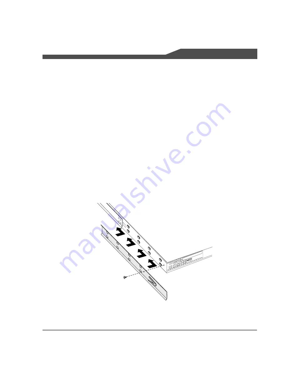
Attach the Sliders to the Chassis

1

Facing the rear of the chassis, take the left-branded inner slider and position it on 

the left side toward the rear of the chassis. The tongues on the chassis should fit 

through the rectangular holes on the rail, and the release mechanism should be 

facing out. 

2

Slide the rail forward, and continue to slide until you can feel that it’s attached 

securely.

3

Fasten with the rail attachment Phillips screw.

4

Repeat Steps 1 through 3 for the right-branded inner slider.

Summary of Contents for Snap Server 700i Series

Page 1: ...o physical harm or loss of data 1 To start the shutdown process push the power button on the front of the server The system LED blinks 3 times per second and the green power LED remains lit until the shutdown process is complete Do not disconnect the AC power cord while the power LED remains lit 2 After the power LED is off disconnect the AC power cord and all other cables from the back of the ser...

Page 2: ...then slide the cover off of the rear of the server and set it aside Installing a Second Power Supply Module 1 The electrical connectors for a second power supply are protected by a piece of metal Take a screwdriver or other tool and break off the plastic covering see illustration Also remove the vented cover on the rear of the unit covering the opening for the second power supply 2 Install the sec...

Page 3: ... the way into the chassis The latch will click in to indicate when it is locked 3 You can now replace the top cover Lower the cover onto the server pushing it forward from the rear of the server until it is firmly seated and replace the screw on the right side of the server 4 Fold the handle down against the module Restoring Power to the Server 1 If you removed the server from the rack replace it ...

Page 4: ...front of the server The system LED blinks 3 times per second and the green power LED remains lit until the shutdown process is complete Do not disconnect the AC power cord while the power LED remains lit 2 After the power LED is off disconnect the AC power cord and all other cables from the back of the server 3 The server is heavy With the help of another person remove the server from the rack to ...

Page 5: ... of the chassis catching the body of the module in the other hand and set it aside Inserting a Replacement Power Supply Module 1 Resting the body of the module in one hand while holding the handle with the other insert the module and slide firmly into place Make sure it is seated all the way into the chassis 2 The latch will lock the module into place Fold the handle down against the module 3 Inse...

Page 6: ...e Server Caution Shut down the server before you make any repairs Improper shutdown may lead to physical harm or loss of data 1 To start the shutdown process push the power button on the front of the server The system LED blinks 3 times per second and the green power LED remains lit until the shutdown process is complete Do not disconnect the AC power cord while the power LED remains lit 2 After t...

Page 7: ...o change without notice and does not represent a commitment on the part of Adaptec or any of its subsidiaries Removing the Top Cover 1 To release the cover first remove the Phillips screw on the right side of the server see illustration 2 With both thumbs press the buttons on the top of the cover then slide the cover off of the rear of the server and set it aside ...

Page 8: ...e one on the rear of the chassis and the other on the motherboard see illustration Loosen the thumbscrews you may need to use a screwdriver Replacing a SAS HBA 1 Carefully lift the riser but do not pull the SAS cable attached to the SAS card Invert the cage to expose the SAS connector on the card Squeeze the buttons on either side of the SAS cable connector and remove the cable 2 Unscrew the brack...

Page 9: ...nto the appropriate PCI slot snap it in place and screw in the PCI card bracket 2 Replace the expansion cage in the chassis and tighten the two thumbscrews Replacing the Top Cover Be sure to replace the top cover Do not operate the server if the cover is not in place 1 Lower the top cover onto the server 2 From the rear of the server push the cover forward until it is firmly seated 3 Replace the s...

Page 10: ... Front Bezel Removing the Front Bezel 1 Press the latches one on each side of the front bezel 2 Still holding the latches in the release position pull the bezel away from the chassis Replacing the Front Bezel 1 Position the new bezel so the tabs line up to slide under the top edge of the cover Make sure the LED LCD connector on the bezel matches up with the connector on the chassis 2 Press firmly ...

Page 11: ...l harm or loss of data 1 To start the shutdown process push the power button on the front of the server The system LED blinks 3 times per second and the green power LED remains lit until the shutdown process is complete Do not disconnect the AC power cord while the power LED remains lit 2 After the power LED is off disconnect the AC power cord and all other cables from the back of the server 3 The...

Page 12: ...he rear of the server and set it aside Removing a Failed Fan Module The Snap Server 700i has two types of fans Chassis fans Fan 1 and Fan 5 and CPU fans Fan 2 and Fan 3 1 Determine which fan has failed a Launch Adaptec Storage Manager b In the Enterprise view click the server with the fan problem then right click the Enclosure Management Device to the right of the disk icons c In the Properties wi...

Page 13: ...ce and does not represent a commitment on the part of Adaptec or any of its subsidiaries Snap Server 700i Series Replacing a Fan Module 2 To remove a failed fan module unplug the cable and lift the module out of the unit Note Needlenose pliers may be required to remove the cable on Fan 1 3 Set the module aside Cable Fan 5 Fan 3 Fan 2 Fan 1 ...

Page 14: ...n are properly seated in the enclosure Note You may need a pair of needle nose pliers to connect the cable on Fan 1 Replacing the Top Cover Be sure to replace the top cover Do not operate the server if the top cover is not in place 1 Lower the top cover onto the server 2 From the rear of the server push the cover forward until it is firmly seated 3 Replace the screw on the right side of the server...

Page 15: ...disk status and activity If a disk drive fails the status light for the failed drive glows amber Back Up the System Contents Before replacing the failed disk drive perform a backup of your system s contents using your standard backup application Status LED Activity LED Status Light Activity Light Condition of Disk Drive Solid green Off Disk drive installed properly but is not active Solid green Bl...

Page 16: ...n the part of Adaptec or any of its subsidiaries Remove the Front Bezel 1 Press the latches one on each side of the front bezel 2 Still holding the latches in the release position pull the bezel away from the chassis Hot Swap Remove and Replace the Failed Disk Drive 1 Check the LEDs on the disk drive carrier to verify that you are physically removing the failed drive The middle LED of the failed d...

Page 17: ...handle releases 3 Remove the failed disk drive by pulling its handle until the drive is out of the chassis 4 Release the latch on the new disk drive and open its handle The handle must be open for you to insert the disk drive all the way into its bay Note In these instructions a new disk drive is one that has never been installed in a Snap Server before 5 Insert the new disk drive into the empty d...

Page 18: ...lick when the latches lock Configure the Replacement Disk Drive If the Pool was Protected by a Hot Spare If the pool was protected by a hot spare the hot spare is automatically incorporated into the pool and takes over for the failed drive Use your replacement drive to create a new hot spare 1 In the Enterprise View select the iSCSI Storage Appliance associated with the hot spare 2 In the Physical...

Page 19: ...erver Caution Failure to use qualified DIMMs supplied by Adaptec may seriously impact data availability could potentially lead to data loss and corruption and will void your warranty Install DIMMs in the proper order Make sure you install the DIMMs in the proper DIMM slots and in the proper order The DIMM slots are labeled on the motherboard as shown below Install the DIMMs in the following order ...

Page 20: ... With the help of another person remove the server from the rack to a clean surface with ample room to the front and rear See the FRU procedure Installing the Snap Server in a Rack for instructions on removing the server from the rack Removing the Top Cover 1 To release the cover first remove the Phillips screw on the right side of the server see illustration 2 With both thumbs press the buttons o...

Page 21: ... only replace the DIMM with another DIMM supplied by Adaptec 2 Remove the DIMM To release the DIMM from its slot press the white latches on both sides of the module down and outward Grasping the edges of the module lift it out of its slot and set it aside 3 Insert the new module into the same slot Grasping only the edges of the module insert it into the same slot avoiding contact with metal surfac...

Page 22: ...grade DIMM in the following order as viewed from the front of the server Replacing the Top Cover Be sure to replace the top cover Do not operate the server if the top cover is not in place 1 Lower the top cover onto the server 2 From the rear of the server push the cover forward until it is firmly seated 3 Replace the screw on the right side of the server Restoring Power to the Server 1 If you rem...

Page 23: ...attach to the rack and a packet of screws for mounting the rails to the chassis and to the rack The rails are not universal They are stamped Left and Right and must be mounted correctly You will need a Phillips screwdriver to mount the rails and a second person to help position the Snap Server into the rack Attach the Sliders to the Chassis 1 Facing the rear of the chassis take the left branded in...

Page 24: ... not represent a commitment on the part of Adaptec or any of its subsidiaries Attach the Slide Rail Assemblies to the Rack 1 Assemble the outer slide rail assemblies by a fitting the longer rail piece on top of the shorter rail piece and b pulling outward until the two pieces lock 2 Position one of the rail assemblies in the rack making sure you place the right branded rail on the right side of th...

Page 25: ...r 700i Series Installing the Snap Server in a Rack 3 Align the front holes with the front holes in the rack and screw a rail screw into the bottom hole Note The rack holes are not evenly spaced Be sure to align the rail so that the rail holes match up with the rack holes 4 Align the holes on the rear of the rack with the rail holes and screw rail screws into the top and bottom holes 5 Repeat Steps...

Page 26: ...ce and does not represent a commitment on the part of Adaptec or any of its subsidiaries Mount the Chassis in the Rack 1 Align the inner sliders attached to the chassis with the front ends of the slide rail assemblies attached to the rack and slide the server into the rack 2 Line up the holes on the inner sliders with the holes on the rack outer rails and secure the chassis with the remaining scre...

Page 27: ... Snap Server is installed in the rack it locks into place To remove the server perform the following steps 1 Unscrew the screws securing the server on the front and rear of the rack 2 Slide the server forward as shown in the illustration 3 Once the server is extended press the release mechanisms on the inner rails attached to the chassis down at the same time and slide the server the rest of the w...

Reviews: