background image


4.0 CFW 

DESCRIPTION 


The CFW scales have an enclosure with all components mounted within 
it.  To gain access to the components remove the 6 screws securing the 
cover to the base. 
 
The basic unit includes: 
 
 Load 

cell 

Pan 


Load Cell frame 


Transformer / External adapter 


Main PCB assembly with display 

 Battery 
 Keypad 


All models of CFW are similar except the selection of load cells and the 
program. 
 
The main circuit board is similar to that used in the CFC scales.  
Normally if a problem is found with a circuit board the most cost effective 
method of solving the problem is to replace the circuit board. 
 
The main PCB assembly includes:  
 

Sections for load cell input filter 
A/D converter (AU1),   
Microprocessor and support circuits (U1, U4) 
Power supply / battery charger circuits (U5, T2) 


@Adam Equipment Company 2007


7

Summary of Contents for CFW Series

Page 1: ...Adam Equipment CFW SERIES SERVICE MANUAL ADAM EQUIPMENT CO LTD P N 7953 Rev A2 February 2007 Adam Equipment Company 2007 ...

Page 2: ... Adam Equipment Company 2007 ...

Page 3: ...E 5 3 0 ERROR CODES 6 4 0 CFW DESCRIPTION 7 5 0 CFW USER PARAMETERS 8 6 0 CFW USER CALIBRATION 11 7 0 FACTORY PROGRAMMING AND CALIBRATION 12 8 0 LOAD CELL DAMAGE 14 9 0 REPLACEMENT PARTS AND ACCESSORIES 17 10 0 SCHEMATICS 18 Adam Equipment Company 2007 3 ...

Page 4: ...ct telephone e mail fax or any other methods B Details of the unit purchased This part of information should always be available for any future correspondence We suggest you to fill in this form as soon as the unit is received and keep a print out in your record for ready reference Model name of the scale Serial number of the unit Software revision number Displayed when power is first turned on Da...

Page 5: ...through table Temperature changed dramatically Electronics faulty Battery low Weight value incorrect Calibration error Recalibrate Unit calibrated with inaccurate weight Balance not level Obstruction between sample and cover Wrong unit of weight displayed Cannot use Full Capacity Over load Stops hitting pan support or hitting bottom of load cell Electronics faulty Parameters set incorrectly Load C...

Page 6: ...ry re zeroing again Use the Tare key to set the display to zero value If the problem persists contact your dealer or Adam Equipment for assistance Err 6 A D out of range The values from the A D converter are outside the normal range Remove the weight from the scale if overloaded Make sure the pan is attached Indicates the load cell or the electronics may be faulty If the problem persists contact y...

Page 7: ...ery Keypad All models of CFW are similar except the selection of load cells and the program The main circuit board is similar to that used in the CFC scales Normally if a problem is found with a circuit board the most cost effective method of solving the problem is to replace the circuit board The main PCB assembly includes Sections for load cell input filter A D converter AU1 Microprocessor and s...

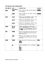
Page 8: ... or the Units Î key to move the active flashing digit to the left or to the right and use the Tare Ï key to increment the flashing digit Press the Zero Enter key to enter the changed value Use the Print Esc key to leave the parameter For example When the display shows F0 H L press the Zero Enter key The display will show SEt Lo the sub parameter Press Zero Enter to set the low limit or press the T...

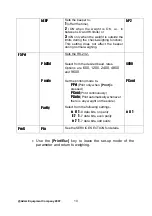
Page 9: ...ion Total in the memory but does not clear the memory F2 unt Ut oFF Ut on Enables or disables the weighing units Use the Zero Enter key to select the weighing unit to enable disable Use the Tare Ï to change the unit to ON or OFF SEt dA Sets the date Display will show the last date set or 00 01 01 Enter the new date format is yy mm dd F3 tI SEt tI Sets the time Display will show the current time En...

Page 10: ...esired baud rates Options are 600 1200 2400 4800 and 9600 Set the printing mode to P Prt Print only when Print is pressed P Cont Print continuously P Auto Print automatically whenever there is any weight on the scale Select from the following settings n 8 1 8 data bits no parity E 7 1 7 data bits even parity o 7 1 7 data bits odd parity 4800 P Cont n 8 1 ProG Pin See the SERVICE SECTION for detail...

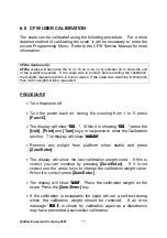
Page 11: ... to 0 press Func C The display will show CAL While it is showing CAL press the Unit Print and Tare keys in sequence to enter the Calibration section The display will show unLoAd Remove any weight from platform when stable and press Zero Enter The display will show the last calibration weight used If this is correct you can continue by pressing Zero Enter If it is not correct use the arrow keys to ...

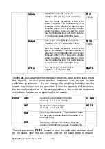
Page 12: ...int keys in sequence to enter the Programming Calibration menu The display will show P1 rEF Press Zero Enter to set the functions of P1 rEF The Programming Parameter PROG has a number of sub parameters that allow the scale to be customised for the application The P1 rEF sub parameter includes many functions that can affect the metrology of the scale These functions should not be reset to other val...

Page 13: ...speed Options 7 5 15 30 or 60 SPd 15 The P2 CAL sub parameter has the basic functions used by the scale to set the capacity decimal point position increment size as well as the calibration procedures Do not change the weighing functions as the scales may not perform as specified Either the capacity will be wrong the decimal point will be in the wrong position or the scale will increment with value...

Page 14: ...ry default settings Press Zero Enter to continue or Print Esc to abort Once the value is set use Print Esc to return to sub parameter Pressing Print Esc again will return the scale to normal weighing 8 0 LOAD CELL DAMAGE The most common reason a scale fails is that the load cell has been damaged The damage can be from 2 primary causes The first is physical damage due to an overload or an impact fr...

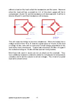
Page 15: ...L 10 VOLT POWER SUPPLY Vout 0 028 VOLTS 28mv BETWEEN S AND s This will cause the bridge to become unbalanced When the bridge has a voltage across it from E to E then the signal output at S and S will show a voltage of zero volts with no load and a small voltage proportional to the load as the load is increased Typical load cells show 20 30mv of signal if the excitation voltage is 10volts and the l...

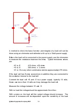
Page 16: ...es Typical resistance values are E to E 410 ohms 30 ohms S to S 350 ohms 2 ohms E to S or any other combination similar approximately 270 ohms If the load cell has Sense connections in addition they are connected to the excitation internal to the load cell Connect the load cell E and E to a power supply typically 10 volts Never use more than 12 volts as it may damage the load cell Measure the volt...

Page 17: ...damaged the no load voltage will likely be greater than 3mv or the loaded voltage will be grossly different from the expected value Remember the loaded voltage will be offset by the amount of zero load voltage measured The load cell can be tested while it is connected to the A D converter circuit board using the scale power supply for excitation voltage 9 0 REPLACEMENT PARTS AND ACCESSORIES If you...

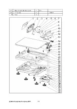
Page 18: ...ndicator bracket parts2 1 ABS 16 indicator bracket parts3 1 ABS 17 nut 1 S18C M6 18 washer 1 SPCC 11 8x7 5 19 hexagon screw 1 S18C M6x20 20 pan 1 SUS304 420mmx520mm 21 internal hexagon screw 8 S18C M8x30 22 spring washer 8 S18C 14x8 5 23 internal hexagon screw 4 S18C M8x50 24 load cell upper bracket 1 AL 25 load cell 1 AL 26 pole 1 SUS304 38x660 27 screw 2 M4x6 28 cable clamp 2 29 load cell lower ...

Page 19: ...37 Base to pole bracket cover 1 AL 38 screw 1 M6x8 39 foot 4 Adam Equipment Company 2007 19 ...

Page 20: ...in the original packaging and with correct documentation for a claim to be processed All claims are at the sole discretion of Adam Equipment This warranty does not cover equipment where defects or poor performance is due to misuse accidental damage exposure to radioactive or corrosive materials negligence faulty installation unauthorised modifications or attempted repair or failure to observe the ...

Page 21: ...ly to cause harmful interference in which case the user will be required to correct the interference at his own expense Shielded interconnect cables must be employed with this equipment to insure compliance with the pertinent RF emission limits governing this device Changes or modifications not expressly approved by Adam Equipment could void the user s authority to operate the equipment WEEE COMPL...

Page 22: ...ans without the prior permission of Adam Equipment Adam Equipment reserves the right to make changes to the technology features specifications and design of the equipment without notice All information contained within this publication is to the best of our knowledge timely complete and accurate when issued However we are not responsible for misinterpretations which may result from the reading of ...

Reviews: