8
TECH TANK
5. DI FLOW
DIGITAL METER
; DI FLOW IN-LINE
DIGITAL FLOW METER
3. INSTALLATION AND USE
3.1 DISPLAY ORIENTATION
The meter is supplied with a calibration carried
out for liquid diesel at 20 °C. Calibration is
required when metering a different fluid, after
disassembly, at different temperature or after
significant wear. A proving container or a con-
tainer of KNOWN volume will be needed for the
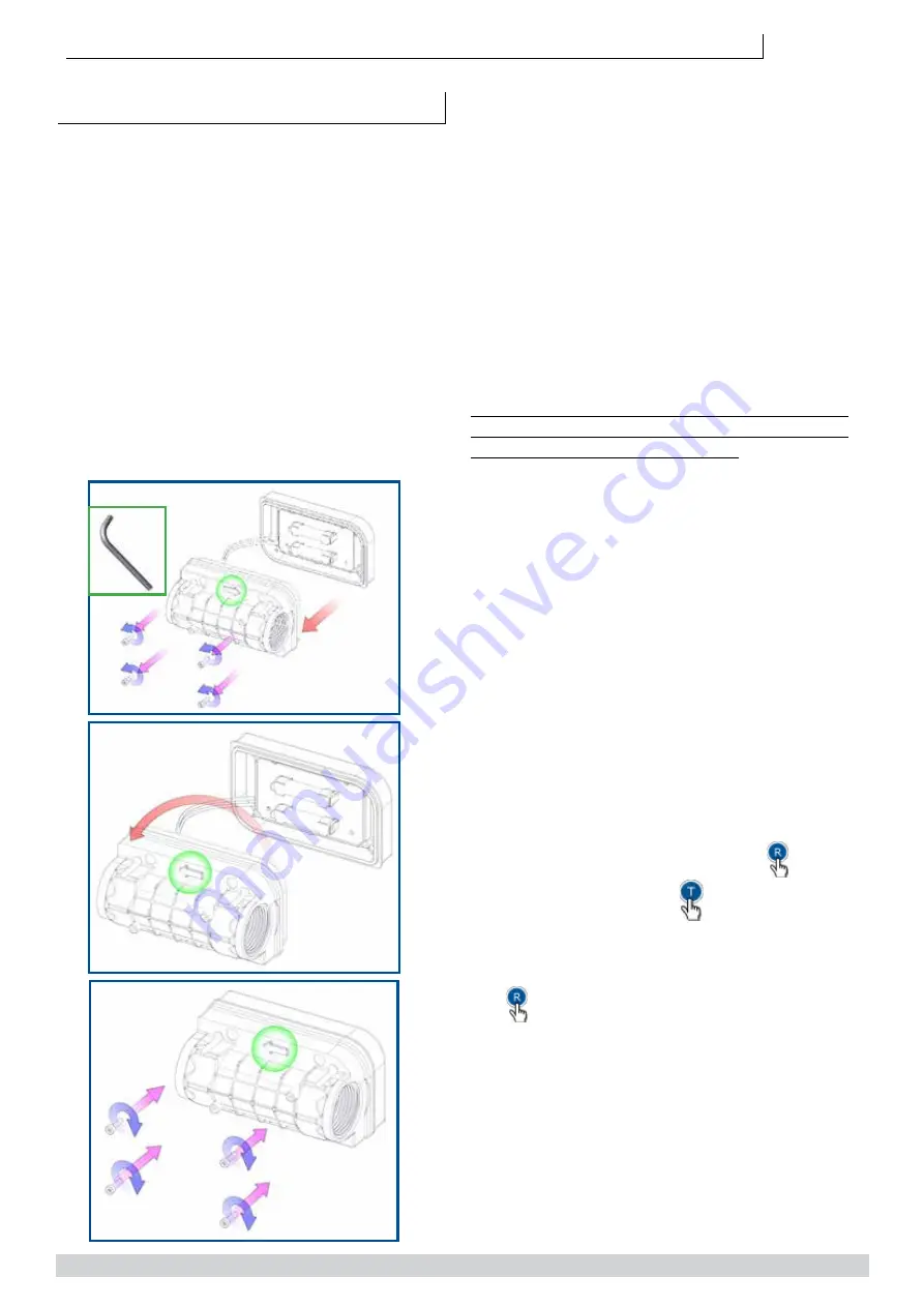
calibration procedure. It is possible to invert the
flow direction using following steps:
1. Remove the 4 screws from the back of the
meter
2. Rotate the meter body by 180°
3. Reposition the body on the cover taking care of
not squeezing wires.
4. Screw the 4 screws to tighten the body to the
cover.
3.2 CONNECTIONS
When adding the flow meter to a existing sys-
tem, connect the flow meter inlet to the outlet
at of the pump, and connect the delivery
hose into the flow meter outlet. It is important
to respect the flow direction looking at the arrows
on the meter body. In case you need the opposite
flow, rotate the meter as described above in para-
graph 3.1.
The meter has a double Reed switch system to
avoid false readings due to vibrations or erroneous
installation and turbine reverse rotation. The meter
is threaded 1” BSP-P female both at inlet and out-
let. Sealing is made using O - ring 30x3 70Sh.
1
2
3
2.5
It is necessary, if not already installed in the
system, to install a filter or screen of at least
40 mesh prior to the flow meter
.
3.2.1 ELECTRICAL WIRING FOR PULSER
VERSION
If you bought our pulser model, the flowmeter is
fitted with a 2m cable with 5 internal wirers to be
connected as follows:
1. Yellow wire: power + 12 Vdc
2. Brown wire: power 0 Vdc
3. Green wire: pulser channel 100 imp/unit
4. White and grey wires: Relay contact should you
desire to control the pump with the meter ( max
24Vdc 500mAh)
Once connected to power supply, the meter will
“Beep”, this sound beeps at each button pressure
(this happens only with pulser version).
It is important to know that the system is genera-
ting pulses 0-12Vdc with maximum frequency 2
milliseconds.
Should the meter control the pump, the
button
will activate the pump while
button stops it.
Two default settings are available and settable in
the system:
1. 60 seconds: to start the transaction after pres-
sing button
2. 20 seconds: seconds without pulse will stop the
transaction.


