background image

ENGLISH (TRANSLATION OF ORIGINAL INSTRUCTIONS)

 WARNINGS! Never leave the filling position to prevent accidental diesel fuel spillage. Do 

not start the pump before having connected the suction and discharge pipes. Do not start 

or stop the pump by inserting or unplugging any plugs. Do not touch any switches with wet 

hands. Avoid direct contact of the diesel fuel with skin or eyes as it may cause harm. Use of 

goggles and gloves is recommended.The single-phase motors are fitted with motor protectors 

and systems against accidental restart. In the event of a power failure, remember to switch 

the pump off and unplug it before restoring it.Work cycles that are continuous or in extreme 

5.4 - e

lectrIcal


connectIon


of


the


pump

SINGLE-PHASE MOTORS

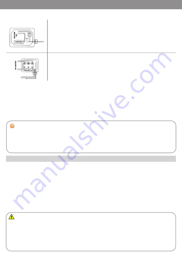
Pumps with single-phase motors are supplied with a 2 m cable and plug.  

To change the power cable, open the capacitor box cover and follow the connection diagram to the 

side.  

Single-phase motors are equipped with phase capacitor and double-pole switch. 

The capacitor specifications are indicated for each model on the pump’s rating plate. 

THREE-PHASE MOTORS

Pumps with three-phase motors are supplied with capacitor box and terminal board.  

To connect the electric motor to the power line, open the capacitor box cover and follow the 

connection diagram to the side. 

For proper installation and electrical maintenance of the system, please follow these instructions:

- make sure the power lines are not live when installing or carrying out maintenance operations on the

system

- use cables with minimum section, rated voltages and type of installation suitable for the system’s

specifications

- make sure the three-phase motors are rotating in the right direction

- always connect the pump’s earth terminal to the electricity grid’s earth line.

6 - INTENDED USE

6.1 - p

relImInary


checks


and


start

-

up

After ensuring there is diesel fuel in the suction tank, that all pipes and components on the hydraulic 

line are in good condition and properly sealed, and the nozzle is closed, the pump can be started. After 

inserting the nozzle into the filling hole, switch the pump on, gradually release the nozzle lever and start 

transferring the diesel fuel. When you have finished filling, close the nozzle and switch the pump off. If you 

are using an automatic nozzle, it will automatically close as soon as you have finished filling.

 CAUTION! The pumps are provided without safety devices such as fuses, motor protectors, 

systems against accidental restart after a power failure. Even the switch, if any, will only start/

stop the pump and can in no way replace a suitable circuit breaker. It is therefore the direct 

responsibility of the installer to connect the pump to the main electrical panel in compliance with 

the regulations in force in the country of use.

Summary of Contents for PA 8050

Page 1: ...ity Directive 2014 35 EU of the European Parliament and of the Council of 26 February 2014 on the harmonisation of the laws of the Member States relating to the making available on the market of electrical equipment designed for use within certain voltage limits Directive 2014 68 EU of the European Parliament and of the Council of 15 May 2014 on the harmonisation of the laws of the Member States r...

Page 2: ... suction and discharge lines 5 4 Electrical connection of the pump 6 INTENDED USE 6 1 Preliminary checks and start up 6 2 Daily use 6 3 Noise level 6 4 Compatibility in an electromagnetic environment 7 TROUBLESHOOTING 8 MAINTENANCE 9 DEMOLITION AND DISPOSAL 10 WARRANTY 11 TECHNICAL SUPPORT 12 ATTACHMENTS 12 1 Exploded views and spare parts list 12 2 Wiring diagrams 12 3 Overall dimensions and weig...

Page 3: ...L POWER SUPPLY MAXIMUM CURRENT AMP RATED POWER WATT WORK CYCLE MIN MAX FLOW RATE L MIN INPUT OUTPUT BSP G NOISE DBA PA1 70A 230V 50Hz AC 230V 50Hz 2 9 552W S1 Continuous 70 1 1 70 PA1 70A 230V 60Hz AC 230V 60Hz 3 5 667W S1 Continuous 70 1 1 70 PA1 70A 380V 50Hz AC 380V 50Hz 1 304W S1 Continuous 70 1 1 70 PA2 80 230V 50Hz AC 230V 50Hz 3 5 700W S1 Continuous 80 1 1 80 PA2 100 230V 50Hz AC 230V 50Hz ...

Page 4: ...sition pump axis either horizontal or vertical in a place sheltered from 4 TRANSPORT AND HANDLING 4 1 Transport The weight and dimensions of the pump allow it to be easily transported by hand The pump does not require lifting equipment to move it 3 3 Allowed fluids forbidden fluids Allowed DIESEL FUEL with 2 to 5 5 cSt viscosity at 38 C Minimum flash point MF 55 C Forbidden PETROL FLAMMABLE LIQUID...

Page 5: ... cavitation phenomena can start with consequent reduction of the flow rate and increase in noise To prevent this phenomenon from occurring it is important to ensure low suction negative pressure by using short pipes or pipes with a diameter larger than or the same as those recommended minimising bends and using large section suction filters and foot valves with the least resistance possible Moreov...

Page 6: ...iagram to the side For proper installation and electrical maintenance of the system please follow these instructions make sure the power lines are not live when installing or carrying out maintenance operations on the system use cables with minimum section rated voltages and type of installation suitable for the system s specifications make sure the three phase motors are rotating in the right dir...

Page 7: ...ump The machine is designed to operate correctly in an industrial electromagnetic environment and staying within the Emission and Immunity limits laid down in the following Harmonised Standards IEC EN 61000 6 2 Electromagnetic compatibility EMC Generic standards Immunity for industrial environments IEC EN 61000 6 4 Electromagnetic compatibility EMC Generic standards Emission standard for industria...

Page 8: ... Replace the damaged components Excessive negative pressure to the suction line Make sure there are no leaks or restrictions on the suction part recommended pipes chap 5 2 High pressure drops in the circuit Change the hydraulic discharge configuration Bypass valve open or blocked Check the condition of the valve and clean or replace it if necessary Vanes blocked Check and clean the vanes and their...

Page 9: ...eel are usually recycled by companies specialised in the scrap metal industry ELECTRICAL AND ELEC TRONIC COMPONENTS These must be disposed of by companies specialised in disposing of electronic components in compliance with the requirements of Directive 2002 96 EC see Directive text below PARTS OF A DIFFERENT NATURE Other parts of the system in which the electric pump is installed such as pipes ru...

Page 10: ... out only by Adam Pumps or by Adam Pumps authorised centres the warranty will not be valid in the event the product is tampered with by unauthorised persons bodies and or companies any warranty request is subject to approval by Adam Pumps The goods can be returned only if provided with an authorisation code Upon request Adam Pumps will provide this code which will invoke the warranty for the produ...

Page 11: ...pring 10X19X7 1 7 OR039 O RING NBR70 57x2 1 8 PA018 swivel locking plate 1 9 PA019 inox filter16x49 1 10 PA020 Capacitor 12 5 μF 450 V 1 11 PA024 bracket block capacitor 1 12 PA025 fan MEC 63 1 13 PA026 fan mec 63 ring ø12 1 14 PA029 cylindrical spacer ø12 4X16 H11 1 15 CP009X body pump pa 70l x treme 1 16 PA021 pin 3x3x15 UNI 6604 B 1 17 61000003 impeller Ø45 1 18 71000522 small vane 5 POS CODE D...

Page 12: ...ld mec 71 15502600000x 1 16 tie rod m5 x 135 znb 6100450000z 4 17 fan mec 71 ring ø14 140260400000 1 18 fan cover mec 71 140260500000 1 19 key 6 x 6 x 20 90505050000 1 20 capacitor 190061000000 1 POS DESCRIPTION CODE QTY 21 black power cable 190200000000 1 22 bypass valve 71000520 1 23 pump body 80l 1 bsp g 71000060 1 24 bypass spring 16001005 1 25 plate 71000521 1 26 or 3118 nbr 18001008 1 27 cap...

Page 13: ...l filter 41410000 1 7 or 3118 nbr 18001008 1 8 cap 1 17001094 1 9 filter plate 71000587 1 10 filter cleaning plate 71000546 1 11 sealing ring 20307 12001015020 1 12 impeller ø72 61000010 1 13 large vane 71000569 7 14 or 85 x 3 nbr 18001022 1 15 large disc 71000063 1 16 socket head screw m5 x 16 znb 13001007 4 17 danger label 71000653 1 18 ce label 220000000000 1 19 thread protection cap ø31 163013...

Page 14: ... protection cap ø31 163013500000 2 7 pump body 150l 71000061 1 8 bypass valve 71000520 1 9 bypass spring 16001005 1 10 plate 71000521 1 11 sealing ring 20x30x7 SNBR 12001015020 1 12 large stainless steel filter 41410000 1 13 O Ring 3118 NBR 18001008 1 14 cap 1 17001094 1 15 filter label 71000587 1 16 key 6x6x20 UNI 6604 A 90505050000 1 17 ce label 1 18 motor 150l me002 1 19 danger label 71000653 1...

Page 15: ...ECH 230 Vac da 60 80 100 L Denominazione 1 1 Scala Materiale Revisioni Rev RM n Data Firma anicardi M 11 2014 1 e generali N 22768 mK Peso indicativo 27 11 2014 Data Stassi Davide Approvato 2 3 4 6 8 5 7 9 1 2 3 4 rietà SCHEMA ELETTRICO L N S1 M A C 230 Vac C1 T S1 Interruttore ON OFF Cs 1 2 3 4 ENGLISH TRANSLATION OF ORIGINAL INSTRUCTIONS EN PA1 70 PA2 80 PA2 100 PA3 150 12 2 Wiring diagrams S1 O...

Page 16: ...00 PA 1 70 Proprietà della ADAM PUMPS Spa Senza autorizzazione scritta della stessa il presente disegno non potrà essere comunque utilizzato per la costruzione dell oggetto rappresentato nè venire comunicato a terzi o riprodotto La società proprietaria tutela i propri diritti a rigore di legge A 7000 ENGLISH TRANSLATION OF ORIGINAL INSTRUCTIONS 12 3 Overall dimensions and weights ...

Reviews: