background image

User’s Guide

Slate Tone Generator

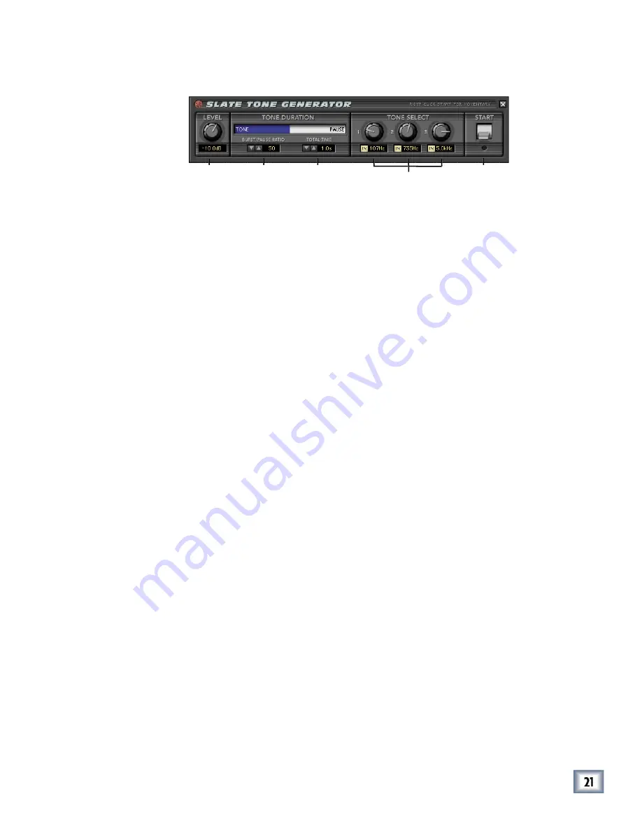
The Slate Tone Generator 

The familiar three-step oscillated tone sequences (like we used to hear at the be-

ginning of cassette albums), are known as Slate Tones. They are used to calibrate 

faders, buses, and meters between consoles and decks to insure that all input and 

output levels are set to a single reference point. Our Slate Tone Generator is de-

signed to give you highly fl exible signals to help you optimize routing in your system. 

Level

Use your mouse to select an output level ranging from off to 0 dB RMS of a full-scale 

sine wave. The reference level is based on 0 dB RMS output values generated by the 

noise generator.

Tone Duration 

Tone duration refers to the amount of tone vs. pause (no sound). These tones have 

adjustable durations that can be customized to suit your needs. Adjust the duration 

by grabbing the tone/ pause bar with your mouse. 

Burst/Pause Ratio

The Burst/Pause Ratio refers to the percentage of burst compared to pause that is 

applied to the generated noise. This pause interval can be assigned to any increment 

between 0 seconds (off) and 100 seconds (full). To adjust the ratio, use your mouse 

to select the up/down arrows, or scroll the numbers in the small window, or grab the 

blue bar graphic and move it left or right.

Total Time (tone sequence) 

Total Time refers to the combined length of tone and pause. Pause can be assigned 

to any interval between 0 seconds (off) and 60 seconds. Use the mouse to select total 

time using the up or down arrows or to scroll the digits.

Tone Select

This lets you choose the frequency of each tone from 16 Hz to 20.0 kHz. Choose 

from standard three-tone oscillator sequences that are generally accepted as indus-

try standards, or customize your own. You can enable or disable individual tones by 

pressing the IN buttons to bring them in or out of play. 

Start

Left-click to start the tone generator, click again to stop. Right-click to play a mo-

mentary tone burst for as long as you hold down the button. 

Level

Tone Select

Start

Total Time

Burst/Pause

Ratio

Summary of Contents for Pro Audio Lab

Page 1: ...S G U I D E ProAudioLab Precision Audio Analysis and Sound Generation Laboratory Precision Audio Analysis and Sound Generation Laboratory Precision Audio Analysis and Sound Plug in for Mackie Digital...

Page 2: ...ll copies thereof This License will terminate immediately without notice from Mackie Designs if you fail to comply with any provisions of this License Upon termination you must destroy the Software an...

Page 3: ...TO PROPERTY OR PERSON OR ATTORNEYS FEES THAT RESULT FROM THE USE OR INABILITY TO USE THE SOFTWARE OR RELATED DOCUMENTATION EVEN IF MACKIE DESIGNS OR A MACKIE DESIGNS AUTHORIZED REPRESENTATIVE HAS BEE...

Page 4: ...Rev A 03 2003 2003 Mackie Designs Inc All Rights Reserved This icon identifies a description of how to perform an action with the mouse This icon will lead you to some further explanations of features...

Page 5: ...The Status Screen 9 The Analysis Screens 10 The Levels Screen 11 Spectrum Analyzer 16 Phase Analyzer 18 The Generation Screens 19 Noise Generator 20 Slate Tone Generator 21 The Oscillator 22 The Pian...

Page 6: ...rms a Pink and White noise generator and Slate tone generation with editable frequencies and burst times Last but not least Pro Audio Lab provides you with dead on tuning references down to semi tones...

Page 7: ...n via the effects return bank Inserting is primarily used on the Master Outputs for concise control during mixdown The tone generator audio returns to the D8B Effects Bank channels that correspond to...

Page 8: ...r 3 To obtain the unlock code have the ESN and plug in serial number ready Then you have two options Log on to the Mackie plug in authorization web page http www mackie com D8Bauthorize htm or Telepho...

Page 9: ...an ner similar to a channel s write button To record automation for a plug in All must be turned on in the automation section of the D8B and automation must be out of Bypass When the D8B is recording...

Page 10: ...rom the Analysis drop down menu found in the Status Screen Only one option can be open at a time The Levels menu is further expandable by clicking on any of the level meters See Page 11 See Page 16 Se...

Page 11: ...y visible guide inserted on the master outputs Obviously it s crucial to avoid digital clipping but it s also important to maintain enough level to sample in the best sounding range of the D8B s gain...

Page 12: ...y helpful in describing the energy of a waveform in RMS values RMS levels are similar to average values and do not vary much even when high transient peaks are presented The ratio between the Peak and...

Page 13: ...99 full scale deflection in 300 ms and overshoot not less than 1 and not more than 1 5 The VU meter is calibrated to display 0 VU for a sine wave at 0 dBFS Loudness A Weighted Level Loudness A Weight...

Page 14: ...e eardrum is most sensitive in the 2 5 kHz to 4 kHz regions The human ear does not hear frequency response as flat and changes substantially depending on the intensity of the sound presented Very Impo...

Page 15: ...gnals are 180 out of phase or 1 indicating that the signals are perfectly in phase 0 means that the two signals are not correlated For most stereo applications a large positive number is typically 0 5...

Page 16: ...rted Range 96 dB to 30 dB The analyzer range enables you to adjust the viewing range of your signal between 96 dB to 30 dB Left Right Buttons Select either right or left channel inputs for viewing Mon...

Page 17: ...o signal caused by audio feedback room equalization prob lems errant filter settings and many other signal problems can be identified more readily and effectively by looking at the signal with this sp...

Page 18: ...ne channel and not the other will display all the points at a 45 angle to the left or right of vertical depend ing on which signal is present A completely uncorrelated signal with equal levels on the...

Page 19: ...eneration drop down menu found in the Status Screen This is where you will find a wide variety of oscillators and tuners to suit any task Only one option can be open at a time See Page 20 See Page 21...

Page 20: ...se to select the up down arrows or scroll the numbers in the small window or grab the blue bar graphic and move it left or right Noise Duration Total Time This refers to the combined length of the bur...

Page 21: ...Ratio refers to the percentage of burst compared to pause that is applied to the generated noise This pause interval can be assigned to any increment between 0 seconds off and 100 seconds full To adju...

Page 22: ...Fine control to fine tune your frequency to an exact setting Tip A good way to approach this is to set your Fine control to its default control click Use the Course control to hone in on the frequency...

Page 23: ...ve tone It may be easier for some to tune to a pure sign wave while the addition of harmonics can often assist in tuning instruments such as bass or the lower two strings of a guitar Semi Tone This of...

Page 24: ...e third fret use the up down arrows to pitch the tuning up three semi tones Wave Select This offers two separate waveforms that can be used as the tuning source tone The squiggly line icon on the left...

Page 25: ...g 0 to 12 refers to the frets on the guitar neck Wave Select This offers two separate waveform options that can be used as the tuning source tone The squiggly line icon is a sine wave with three harmo...

Page 26: ...can be used as the tuning source tone The squiggly line is a sine wave with three harmonics and the sine wave symbol is a pure sine wave tone Cents A frequency range can be fine tuned to zero on a re...

Page 27: ...n to a UFX Card 1 Click the Plugins menu and select Plugins or use the keyboard shortcut Ctrl P 2 In the Plugin Configuration menu locate the card slot that contains the UFX card to which you want to...

Page 28: ...t and right bus or Bus 1 8 When a plug in is inserted in this manner its output is routed directly back into the channel In addition Plugin Chain can be selected as an Input Source which allows you to...

Page 29: ...ick Save to complete the operation To Load a Preset 1 Click Mem A or Mem A or Mem A Mem B to choose the memory location from which to load the file 2 Click and hold the Menu button Menu button Menu 3...

Page 30: ...u want to paste them to a new preset The plug in also reverts to its default state it is reset To Copy Plug in Settings 1 Click and hold the Menu button Menu button Menu 2 Select Copy The current sett...

Page 31: ...the page drop down menu This displays a list of available channel and plug in parameters Note Parameters can be controlled from either the GUI plug in graphic parameters using a mouse to modify the pa...

Page 32: ...nel insert point is selected the plug in output returns to the channel by default The FX return path is disconnected although the plug in output is still dis played on the FX return channel meter A pl...

Page 33: ...according to the example above 3 Use the AUX 4 control to adjust the input level to the plug in Remember Select an aux send before using the V pot or GUI Control Pot on the mixer input channel MIC LIN...

Page 34: ...e or post fader globally all Aux 1 s for instance from the Mix Options screen in the Setup window or individually on a chan nel by channel basis either from the channel strip or the Fat Channel In the...

Page 35: ...tons and FX buttons lower left on the D8B buttons lower left on the D8B buttons lower mixer screen Plugins button opens the Patch Configuration window or Plugins button opens the Patch Configuration w...

Page 36: ...Acuma Pro Audio Lab 2003 Mackie Designs Inc All Rights Reserved...

Reviews: