


Installation Guide
Easyconnect App
6
Installation Guide - Easyconnect App
Document: 9590-4009
Ver. 2 201126
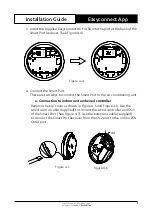
1. Remove the backing plate from the Smart Port Reciever.
Insert a screwdriver into the two slots in the lower part of the Smart Port
Reciever and remove the backing plate. (See Figure 4-2)
8
Fig 4-5
4. INSTALLATION METHOD
4.Remove the upper part of the smart port
For exposed mounting, fasten
the back plate on the wall with
the 3 screws (M4×20) and plugs.
(Fig.4-6)
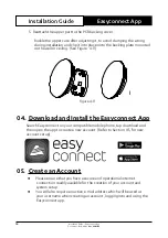
6. Insert the smart kit with slightly strength into the main PCB
of the smart port .(Fig.4-7)
5. Fasten the back plate of the smart port
Slots
Insert a slot screwdriver into the slots in the
lower part of the smart port (2 places), and
remove the upper part of the smart port.
(Fig.4-5)
Fig 4-6
Back plate
Screws (M4×20)
Fig 4-7
Figure 4-2
Slots
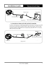
2. Mount the backing plate of the Smart Port Reciever inside the
conditioned area, on the wall or ceiling, as close to the Wi-Fi router as is
practical , using the three screws (M4x20) provided. (See Figure 4-3)
8
Fig 4-5
4. INSTALLATION METHOD
4.Remove the upper part of the smart port
For exposed mounting, fasten
the back plate on the wall with
the 3 screws (M4×20) and plugs.
(Fig.4-6)
6. Insert the smart kit with slightly strength into the main PCB
of the smart port .(Fig.4-7)
5. Fasten the back plate of the smart port
Slots
Insert a slot screwdriver into the slots in the
lower part of the smart port (2 places), and
remove the upper part of the smart port.
(Fig.4-5)
Fig 4-6
Back plate
Screws (M4×20)
Fig 4-7
Figure 4-3
Backing Plate
Screws (M4x20)