


Installation and Commissioning Guide
Classic 2 Outdoor Units
Installation and Commissioning Guide - Classic 2 Split Ducted Outdoor Unit
Doc. No.0525-073 Ver. 8 210414
13
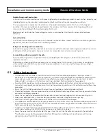
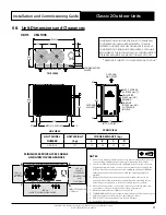
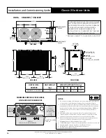
08.03. CRA150S / CRA150T / CCA150S
UNIT MODEL
NUMBER
UNIT WEIGHT
(kg)
CORNER WEIGHTS (kg)
A
B
C
D
CRA150S / CCA150S
133
19
45
22
47
CRA150T
132
20
43
21
48
** DRAWING IS SUBJECT TO CHANGE WITHOUT NOTICE**
CONDENSATION POINTS ARE DESIGNED TO ENSURE ALL
CONDENSATION IS REMOVED EFFICIENTLY TO AVOID
WATER POOLING WITHIN THE CONDENSER. IF A SINGLE
CONDENSATION DRAIN POINT IS REQUIRED, ACTRONAIR
RECOMMENDS THE INSTALLATION OF A CONDENSER TRAY.
THESE ARE AVAILABLE AS AN ADDITIONAL ACCESSORY.
1320 O/A
255
565
255
580
O/A
550
COMP
65
OUTDOOR COIL
OUTDOOR AIR INLET
OUTDOOR
AIR OUTLET
990
O/A
OUTDOOR
AIR INLET
925
35
30
870
110 115
57.5
115
57.5
25
25
517
(MTG C-C DIST)
985
(MTG C-C DIST)
CONDENSATION
POINTS
CONDENSATION
POINTS
TOP VIEW
FRONT VIEW
SIDE VIEW
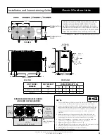
NOTES:
1. Do not scale drawing. All dimensions are in mm unless specified. Refer to
corresponding unit dimensional drawing for mounting hole details.
2. Service Access Areas and Spaces for Airflow Clearances given above are
suggested minimum based on the condition that the spaces around the
units are free from any obstructions and a walkway passage of 1000mm
between the units or between the unit and the outside perimeter is
available.
3. Minimum service access areas and spaces for airflow clearances are
responsibilities of the installer, ActronAir will not be held liable for any
extra charges incurred due to lack of access and space for airflow.
4. Under all circumstances, condenser air must not recirculate back onto
condenser coil. Keep all clearance free of any obstructions.
5. Maximum External Static of Outdoor Fans is 5 Pa.
6. STACKING OF UNITS: Ensure that minimum airflow and clearances are met.
7. Refer to pipe Connection Details on Specifications Sheet.
8. MTG C-C DIST = Mounting Centre to Centre Distance.
9. Use M12 bolt for feet mounting.
THIRD ANGLE
PROJECTION
HEIGHT CLEARANCE
= 1500 mm
B
MINIMUM SERVICE ACCESS AREAS
AND AIRFLOW CLEARANCES
300 mm
SERVICE
CLEARANCE
600 mm
SERVICE
CLEARANCE
(COMPRESSOR
AND
ELECTRICALS
)
OUTDOOR COIL
COMP
NIL - TO - MINIMUM SERVICE CLEARANCE
A
C
400 mm
SERVICE / AIRFLOW CLEARANCE
D


