10
Troubleshooting Guide - Advance Split Ducted Unit
Doc. 9590-2015-03 Ver. 3 221111
Troubleshooting Guide
Advance Split Ducted Unit
04.04. Expected Voltage - InZone PCB To Indoor Fan
INDOOR CPU BOARD
(EVAPORATOR)
FAN POWER
240VAC
TX
AU
X
24
0VA
C
C
O
M
COM
12V
0-10V
12V
S1
0-
1
0V
COM
0-
1
0V
COM
A
S2
B
S3
G
COM
A
A
B
B
G
G
COIL
TEMP
INDOOR FAN
24VAC
TX
PWM
INDOOR
FAN
O
U
TD
OO
R
485
AUX
485
WA
LL
C
O
N
TR
O
L
LE
R
TEMP
SENSORS
AUX
OUT
AUX
IN
ICB
MASTER
WALL CONTROLLER
SECONDARY
MAINS
SMPS 240VAC/12VDC
AC/L
AC/N
V-
V+
A
N
IF-1
1 EC
ECM
CONTROL
MODULE
INDOOR FAN (IF)
INTERNAL AUTO RESET
OVERLOAD PROTECTION
WALL CONTROLLER
ZONE 8
ZONE 7
ZONE 6
ZONE 5
ZONE 4
ZONE 3
ZONE 2
ZONE 1
Step 1.
1. Measure the Indoor Fan on/off signal.
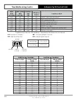
On signal = 12VDC signal between Pin 1 and 3 (red and blue wires).
Off signal = +0VDC signal between Pin 1 and 3.
Step 2.
1. Set the tester to measure duty cycle
.
2. Set the indoor fan to a fixed speed eg High & turn all zones on.
3. Measure the reading between Pin 3 and 4 (blue and yellow wires).
4. Change fan speed and check for any changes in readings.
5. Compare the duty cycle output to the expected PWM for each model.
NOTE
Duty cycle cannot be tested in voltage. A voltage on the PWM line indicates a Duty Cycle is present.


