Installation
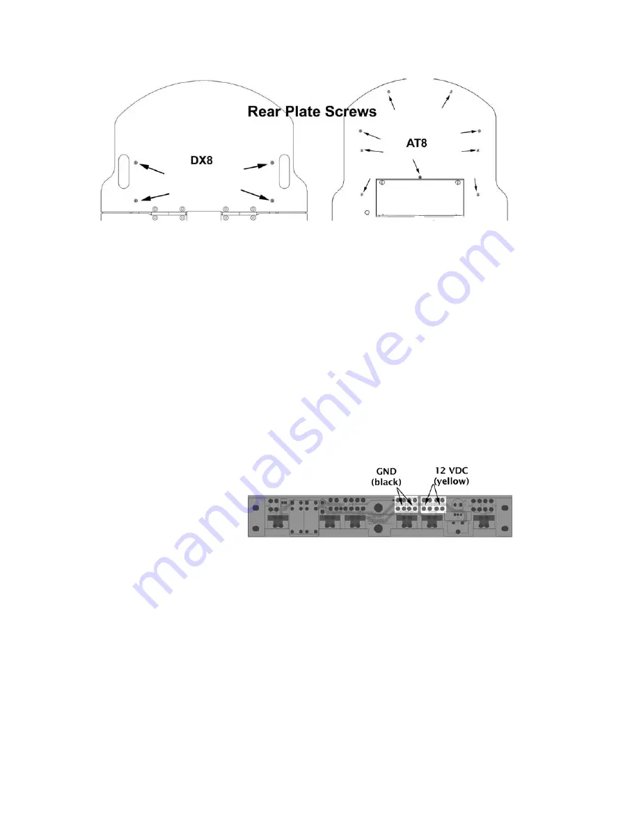
Figure 4. Rear deck screws for the Pioneer 2 robots
S
TEP
4: I
NSTALL
P
OWER AND
C
ONTROL
C
ABLES
Start from the front of the robot and route the Gripper’s signal and power cables to their
respective locations in the body: the signal cable to the controller board and the power
cable to power terminals on the battery board. If you have an onboard PC, we
recommend that you run the cables under the computer, which means that you may
have to loosen, if not remove its four attaching screws and slide the cables underneath.
The power cable should be run through the wiring slots along the right side of the robot.
If you have a P3-AT with onboard computer, run both cables over the top of the
computer and to the respective controller and battery board. Re-install the front half of
the top plate and open the rear half to attach the cables to their respective
terminations. NOTE: If you have a factory installed Gripper, the power cable is attached
to the motor/power board, not the battery board.
Power Cable
Figure 5. Pioneer 2/3 battery board power terminals
At the rear of the robot, on
top of the box that holds the
batteries, locate the main
Power Out screw terminals.
Loosen those screws with a
flat-bladed screwdriver, add
the spade terminal ends of
the Gripper power cable to
that connector--black wire to black wire GND and yellow wire to yellow wire 12 VDC,
then tighten the screws well.
Signal Cable
Locate the User I/O-Gripper connector on your robot’s controller. See Appendix B for
details. Route the Gripper signal ribbon cable and plug it into that IDC connector. Seat
it well so that the latches lock the connector and cable to the board.
S
TEP
5: R
EASSEMBLE
Reverse the process in Steps 2 and 3 to re-attach your Pioneer’s top deck plate. Hold it a
few centimeters above the body and reattach the various cables to the Motor-Power
Interface board.
6


