background image

Comfort Line Products, Inc.  

19

OPERATION

•   Test the GFCI before each use. (Refer to the 

instructions provided in the Maintenance section of 

this manual.)

•   Plug into a properly grounded receptacle.

•   Do not use extension cords.

Temperature Control

1. 

During normal operation, the control display on the top of the 

power pack displays the current water temperature.

2. 

To set the desired water temperature, press and release the up or down 

heat button. The display will flash the desired water temperature 

set point. To change the set point, press the up or down button 

once for each degree of water temperature, to a maximum of 104ºF 

(40ºC).

3. 

After  a  few  seconds  pass  without  pressing  either  heat  button, 

the display will return to the current water temperature. The spa 

will  begin  heating  to  the  desired  water  temperature  at  a  rate  of 

approximately 1 to 1-1/2 degrees F per hour.

4. 

The spa is made to hold the set temperature. Do not lower the  

temperature set point after use. The heater will turn on and off 

automatically to maintain the desired temperature.

5. 

In case of electric power interruption, the spa temperature set point 

will default to 100ºF when electric power is restored.

Summary of Contents for CL 100-C

Page 1: ...Owner s Manual Models CL 100 C CL 250 C CL 250 CSIMW 6 SPA N A BOX 5 SPA N A BOX...

Page 2: ...OT TUB AVERTISSEMENT LES PERSONNES QUI PRENNENT DES M DICAMENTS OU ONT DES PROBL MES DE SANT DEVRAIENT CONSULTER UN M DECIN AVANT D UTILISER UN SPA OU UNE CUVE THERMALE WARNING PEOPLE WITH INFECTIOUS...

Page 3: ...NE RADIO T L VISEUR ETC MOINS DE 1 5 M 5 PIEDS DU SPA OU DE LA CUVE THERMALE CAUTION MAINTAIN WATER CHEMISTRY IN ACCORDANCE WITH MANUFACTURER S INSTRUCTION ATTENTION LA COMPOSITION CHIMIQUE DE L EAU D...

Page 4: ...ldren to use this product unless they are closely supervised at all times A WARNING Risk of Child Drowning Extreme caution must be exercised to prevent unauthorized access by children To avoid acciden...

Page 5: ...y a minimum of 8 SWG 8 4 mm solid copper conductor attached to the wire connector in the Power Pack which is provided for this purpose 10 DANGER Risk of Electrical Shock Do not permit any electrical a...

Page 6: ...and 6 unconsciousness resulting in the danger of drowning F Persons su ering from obesity or with a medical history of heart disease low or high blood pressure circulatory system problems or diabetes...

Page 7: ...e oor loading of your spa If in doubt please consult an architect or engineer to determine the oor rating before ling See speci cations 7 Do not open Power Pack or the GFCI Opening either component wi...

Page 8: ...User s Guide 8...

Page 9: ...ments INDOOR INSTALLATION Give special consideration to the following issues when installing your spa indoors 1 Make sure the oor can support the total spa lled weight of 2569 pounds 2 Install your sp...

Page 10: ...o sharp objects under the spa 2 Do not install the spa on grass or dirt as this will greatly increase the amount of debris entering the spa Stepping stones or a solid wood 8 ft x 8 ft square platform...

Page 11: ...spa have been received and are undamaged Report and missing or damaged parts immediately 1 Air Loop 2 Power Pack 3 GFCI 120 V models only 4 Wall Panels 5 Vinyl Liner 6 In atable Bladder Cover 7 Top Sp...

Page 12: ...panel The snap and lock should be towards the top as shown in the diagram at right Take another panel and slide it into the receiving plastic extrusion you placed on the rst panel Take another plastic...

Page 13: ...Remove label s from liner to powerpack union nut 5 Place the liner inside the spa Unfold and line up ttings with holes in wall panel Push ttings through holes in panel and snap the top of the liner to...

Page 14: ...ctric outlet Press the Turbo Wave On O button to start the in ation NOTE The power pack will make a rattling noise while the pump is running with no water This is normal Do not run the power pack with...

Page 15: ...en the connection nut Next attach the middle and upper hose connections from the power pack to the spa Make sure the hose washers are in place and seated inside the connections Tighten the ttings hand...

Page 16: ...th hands smooth out any wrinkles on bottom of liner starting from the center of liner and proceeding outwards towards the wall Continue lling the spa with water to two inches above the top of the suct...

Page 17: ...d begin pumping water Water should ow from the small return nozzle on the bottom inside wall of the spa behind the power pack If water is not owing from the return nozzle repeat the air bleeding instr...

Page 18: ...Always supervise children around bodies of water The spa cover is not a safety cover The spa cover is not a substitute for adult supervision 8 Connect the eight clips to secure the cover in place The...

Page 19: ...e set point To change the set point press the up or down button once for each degree of water temperature to a maximum of 104 F 40 C 3 After a few seconds pass without pressing either heat button the...

Page 20: ...se Remember at elevated temperatures 15 minutes soaking time is considered safe The spa power pack contains a lter to help keep the water in the spa clean If the lter becomes dirty or clogged water ow...

Page 21: ...liner does get a tear or puncture your dealer can provide you with patching material Patch kits are also available through any local hardware store A secure unnoticeable repair can usually be made Vin...

Page 22: ...eder and retest after another 2 days Avoid punching too many holes in the feeder as this could cause over bromination which could bleach out the liner and void the warranty If the bromine level in the...

Page 23: ...king a vacation or leaving your spa unused for a week or so you should take a few simple precautions Leave the thermal top on turbo control o and set the thermostat dial to low This will allow the pum...

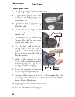
Page 24: ...in the lter housing Make sure the lter is properly seated in the housing and that the o ring is properly seated in the o ring groove 7 Install the lter housing cover and secure with the retaining ring...

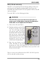
Page 25: ...wave blower 2 Push the test button on the GFCI located at the end of the power cord The GFCI light should go out and the turbo wave blower should shut o If the GFCI light does not go out and the turbo...

Page 26: ...her electrical item into the outlet such as a hair dryer or lamp No power Check the main breaker at fuse box in the house 2 Test the GFCI at the end of the power cord using the instructions in the mai...

Page 27: ...ting close the bleed tting and plug in If the water pump still does not pump water contact the manufacturer for instructions If the water pump becomes air bound again check the o ring on the top of th...

Page 28: ...urther instructions Leaks Symptom Solution Water leaks from between the power pack and the spa 1 The two small hand tight connections leading to the spa are leaking There is a garden hose washer on th...

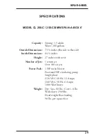
Page 29: ...at side Inside Dimensions 64 inches Height 27 inches with cover Number of Jets 1 return jet Over 100 air jets Power Pack 1 HP turbo blower Fractional HP circulating pump Single phase 120 VAC 60 Hz 12...

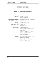
Page 30: ...at side Inside Dimensions 50 inches Height 24 inches with cover Number of Jets 1 return jet Over 100 air jets Power Pack 1 HP turbo blower Fractional HP circulating pump Single phase 120 VAC 60 Hz 12...

Reviews: