background image

   [email protected]

MODEL: S002144 

AFTER SALES SUPPORT


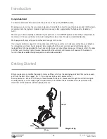
  1800 465 070

9

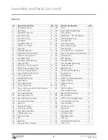
Assembly and Parts List (cont)

Parts List


Nr.    Name & Specification   

Qty    Nr.   

Name & Specification   

Qty   

1  

Handle Bar Foam (1)  

39 

Crank   

1  

Hand Pulse   

40 

Adjust Wheel Gapbushing    

1  

Handle Bar Foam (2) 

41  

Adjust Wheel  

1  

Hand Pulse Wire  

42 

Od14*id10.5 *1.5T  Flat Washer  

1  

Hand Pulse Screw   

43 

M10*6.35t  Nylon Cap   

Handle Bar   

1  

44 

Curve Washer  

1  

Handle Bar End Cap  

45 

Adjust Wheel Fixer  

1  

M5*25  Cross Screw 

1  

46 

Adjust Wheel Spring  

1  

Computer   

1  

47 

Space Washer   

1  

10  

M5*16  Round Screw   

48 

Od20*id10.5*2.0t  Flat Washer  

11  

Od12*id8.5*1.5t  

Flat Washer   

1  

49 

Semi-Circle Washer (with 

φ

12  Axle) 

12  

M8*2.0T  Spring Washer  

50 

Flywheel Axle   

1  

13  

Handle Bar Knob  

1  

51  

6901  Bearing   

1  

14  

Handle Bar Knob Bushing  

1  

52 

Small Belt Roller  

1  

15  

Computer Post  

1  

53 

One Way Bearing Bushing   

1  

16  

Od20*id8.5*1.5t  Arc Washer   

54 

Copper Bushing   

1  

17  

M8*20  Inner Hexagon Screw  

55 

6904  Bearing    


1  

18  

Sensor Wire Upper Section  

1  

56 

HF2016  One Way Bearing  

1  

19  

Lower Computer  Post Cover  

1  

57 

Flywheel Sets   

1  

20 

TCD  Lower Section    

1  

58 

6001 Bearing   

1  

21  

Water Bottle  Bracket  

1  

59 

M5*30  Outer Hexagon Screw  

1  

22 

Water Bottle  

1  

60 

Magnetic Spring  

1  

23 

TCD  Upper Section  

1  

61  

Magnetic Group  

1  

24 

M4*20  Flat Screw   

18  

62 

M5 Nut  

25 

Sensor Wire Lower Section (With Sensor 

and Sensor Fixer) 


1  

63 

M10*100 (25mm) 

Outer Hexagon Screw  


1  

26 

Seat Adjustment Bar 

1  

64 

Rear Stabilizer End Cap    

27 

Seat Adjustment Clip 

1  

65 

Rear Stabilizer  

1  

28 

Seat Adjustment  End Cap  

1  

66 

M8*72  Inner Hexagon Screw  

29 

Seat Adjustment Knob  

1  

67 

Front Stabilizer  end Cap  

30 

Seat Post   

1  

68 

Front StabIlizer  

1  

31  

Seat Post Bushing  

1  

69 

Pedal Strap (L+R) 

32 

Quick Release Knob  

1  

70 

Pedal (L+R)  

33 

Seat (With Towel Rack)


1  

71  

Crank Hole Cover  

34 

M4*8  Round Screw  

1  

72 

Left Body Cover  

1  

35 

Seat Post Cover  

1  

73 

Right Body Cover  

1  

36 

Belt  

1  

74 

Wire Cap  

37 

Belt Plate  

1  

75 

Handle Bar Knob Housing  

1  

38 

Bushing Group (10 pieces)


1  

76 

Main Frame  

1  


Summary of Contents for S002144

Page 1: ...MAGNETIC UPRIGHT EXERCISE BIKE Model Number S002144 INSTRUCTION MANUAL ...

Page 2: ...chase is faulty please telephone our Helpline for immediate assistance Faulty product claims made within the 2 year warranty period will be repaired or replaced free of charge provided that you have satisfactory proof of purchase keep your till receipt safe This does not affect your statutory rights However be aware that the warranty will become null and void if the product is found to have been d...

Page 3: ... 070 3 Contents 2 Introduction 2 Getting Started 4 General Information and Safety Instructions 7 Assembly and Parts List 13 To use the Exercise Bike 14 Console Operation 15 Functions Features 17 Error Message 17 Other Useful Information 18 Workout Area 19 Exploded Diagram ...

Page 4: ...d materials in a safe place It will help prevent any damage if the product needs to be transported in the future Plastic wrapping can be a suffocation hazard so please ensure all packaging materials are kept safely away from children and babies Packaging Disposal Government guidelines ask that we reduce the amount of waste material disposed of in land fill sites We therefore ask that you dispose o...

Page 5: ...and knowledge unless they are being supervised by the person responsible for their safety Keep unsupervised children away from the exercise bike at all times 6 This exercise bike is categorised as Class H and is for home use only It is not intended for commercial use Only use this exercise bike in the manner as described in this manual 7 Keep the exercise bike indoors away from moisture and dust D...

Page 6: ... or keep the equipment out of use until repair 17 Children should be supervised to ensure that they do not play with the appliance 18 This exercise bike conforms to AS4902 1993 WARNING Over exercising may result in serious injury or death If you feel faint stop exercising immediately WARNING Please keep children away from the exercise bike when it is in use This can lead to injuries WARNING Before...

Page 7: ...service actionspares com au MODEL S002144 AFTER SALES SUPPORT 1800 465 070 7 Assembly and Parts List Parts Diagram ...

Page 8: ...cont Hardware List 5mm Allen key Sleeve spanner Multi functional spanner M5 x 25 Screw 1 Piece Spring washer M8 x 2 0T 5 Piece Arc washer 0D20 x 1D8 5 x 1 5T 4 Piece Flat washer OD12 x 1D8 5 x 1 5T 1 Piece Handle bar knob bushing 1 Piece M8 x 72 screw 4 Piece 66 13 8 11 12 14 16 Handle bar knob 1 Piece ...

Page 9: ...asher 8 54 Copper Bushing 1 17 M8 20 Inner Hexagon Screw 4 55 6904 Bearing 1 18 Sensor Wire Upper Section 1 56 HF2016 One Way Bearing 1 19 Lower Computer Post Cover 1 57 Flywheel Sets 1 20 TCD Lower Section 1 58 6001 Bearing 1 21 WaterBottle Bracket 1 59 M5 30 Outer Hexagon Screw 1 22 Water Bottle 1 60 Magnetic Spring 1 23 TCD Upper Section 1 61 Magnetic Group 1 24 M4 20 Flat Screw 18 62 M5 Nut 2 ...

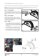
Page 10: ... Step 2 Rear Stabiliser Attach the rear stabiliser 65 to the rear of the main frame Use two M8 x 72 inner hexagon screw 66 M8 spring washer 12 and OD20 x ID8 5 x 1 5T arc washer 16 to lock them up See Fig 2 Step 3 Pedals 1 Attach the pedal straps 69 on to the pedals 70 ensuring the left strap is attached to the left pedal and the right strap is attached to the right pedal See Fig 3 4 5 and 6 2 Att...

Page 11: ...post 15 3 Slide the computer post lower cover 19 onto the computer post 15 and hold it up close to the tension adjustment knob while completing step 4 4 4 Hold the computer post 15 close to the lower computer post and connect the sensor wire upper section 18 with the sensor wire lower section 25 and connect the TCD upper section 23 with the TCD lower section 25 as pictured below 5 Attach the compu...

Page 12: ...the monitor 9 over the top of the monitor post 15 and attach with the M5 x 25 flat screw 8 See Fig 9 Step 7 Seat 5 Place the seat 33 on the seat adjustment bar 26 and use the spanner to tighten it 6 Pull out the quick release knob 32 and insert the seat post 30 into the main frame Adjust to the desired height and re insert the quick release knob 32 to secure Please ensure the quick release knob 32...

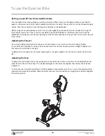
Page 13: ...tep onto the ground You may then step off the machine Adjusting the Tension Increasing or decreasing the tension allows you to add variety to your workout sessions by adjusting the resistance level of the bike To increase tension and increase resistance requiring more strength to pedal turn the Tension Control Knob to the right To decrease tension decrease resistance requiring less strength to ped...

Page 14: ...de or leak Remove batteries from product before extended storage Do not short circuit the supply terminals Batteries may explode or leak if misused The things you should know before exercising A User Data You should input your personal data before workout Press BODY FAT key to enter your personal data of age sex weight and height then the monitor will save the data unless you take out the batterie...

Page 15: ... signal input then the monitor will display NO SPEED on the window 7 DISTANCE Displays the accumulative distance travelled during each workout up to a maximum of 99 9KM 8 CALORIES Your monitor will estimate the cumulative calories burned at any given time during your workout 9 PULSE Your monitor displays your pulse rate in beats per minute during your workout If there is no pulse signal input then...

Page 16: ...ER RESET a Press the key to accept the current data entry b During the NO SPEED mode by holding this key for over two seconds then the monitor will re power on 4 BODY FAT Press the key to enter your personal data before to measure your body fat ratio 5 MEASURE Press the key to get your body fat ratio BMI and BMR a FAT Indicates your body fat percentage after measurement b BMI Body Mass Index BMI i...

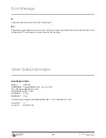
Page 17: ...nal input within 20 seconds then the monitor will display Err You can repress any key to quit the Err message Other Useful Information Specification Table MODEL S002130V DIMENSIONS Assembled dimensions 146 x 60 x 91cm Class HC speed independent system SEAT HEIGHT 84 5cm 103cm NET WEIGHT 27 0kg WARRANTY 2 Year This Bike Trainer complies with Standard ISO 20957 1 2013 ISO 20957 5 2016 Version No 1 2...

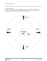
Page 18: ...and training area The free area should be no less than 0 6m greater than the training area in the directions from which the equipment is accessed The free area must also include the area for emergency dismount Where equipment is positioned adjacent to each other the value of the free area may be shared ...

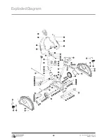
Page 19: ...service actionspares com au MODEL S002144 AFTER SALES SUPPORT 1800 465 070 19 Exploded Diagram ...

Reviews: