www.acti.com
Hardware Manual
14
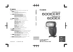
4.
Attach the cable gland body to the hole of the camera.
Attach to Camera Side Hole
Attach to Camera Bottom Hole
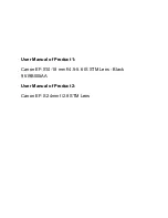
5.
If the cable will be routed along the surface
, skip this step.
If the cable will pass through the surface
, do the following:
a.
Pull the network cable through the bottom conduit hole.
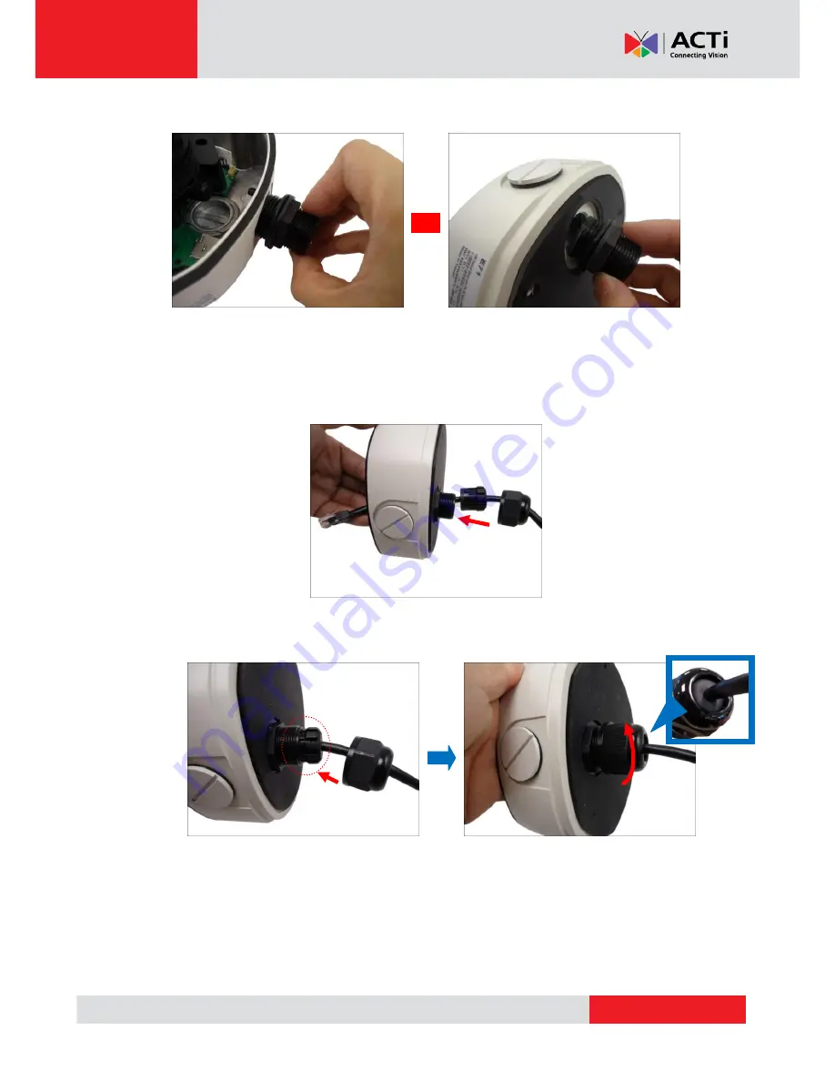
b.
Insert the sealing insert with claw into the cable gland body and then attach the clamping
nut to complete the cable solution.
NOTE:
Make sure the clamping nut is tightly attached to the cable gland body and the sealing
insert is squeezed tightly.
6.
Proceed with
Step 4: Install the Camera to the Surface
on page 19.
or