ACTi Indoor Dome Series E610, Hardware Manual
The ACTi Indoor Dome Series E610 comes with a comprehensive Hardware Manual, available for free download from manualshive.com. This manual provides users with detailed instructions on setting up and maximizing the features of this advanced surveillance camera, ensuring optimal performance and security. Get your manual now!
Share
Download


Reviews:
No comments
Related manuals for Indoor Dome Series E610

ETX900-TSO
Brand: EarthX Pages: 17

ETX Series
Brand: EarthX Pages: 23

evolion
Brand: Saft Pages: 6

UDC7M
Brand: Uniden Pages: 140

WAT-910BD
Brand: Watec Pages: 63

Yi
Brand: Xiaomi Pages: 2

Lumix DMC-FT25
Brand: Panasonic Pages: 24

TNV-C7013RC
Brand: Hanwha Vision Pages: 20

6170.50
Brand: Ikelite Pages: 32

NAC-HD-329VL/60
Brand: Navaio Pages: 2

VHL3Z-19G490-C
Brand: Thinkware Pages: 4
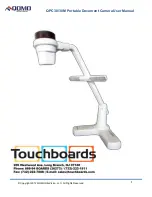
QPC 30M
Brand: Qomo Pages: 10

ED335
Brand: EverFocus Pages: 19

SVC-P
Brand: Smart Witness Pages: 6

TacPole
Brand: Bullard Pages: 4

TTACAMFULLHDLCD
Brand: SBS Pages: 21

9060(A)
Brand: Koukaam Pages: 23

P-HLR
Brand: PROAIM Pages: 3


