background image

24 


1.


Orient the monocular and weapon mount as shown in 
Figure 2-4. Be sure to align the alignment boss on the 
weapon mount with the alignment groove in the monocular. 

2.


Screw in the thumbscrew to secure the monocular to the 
weapon mount. 

3.


Loosen the clamping knob on the weapon mount. Position 
the weapon mount with the monocular onto the weapon’s 
mounting rail. Tighten by turning the clamping knob. 


NOTE 

A RATCHET IN THE WEAPON MOUNT 

PREVENTS OVER TIGHTENING OF 

THE CLAMP. TURN UNTIL THE KNOB 

CLICKS. 


4.


Check the position of the monocular by holding the weapon 
in the normal firing position. Adjust the fore/aft position 
of the monocular as necessary by loosening the clamping 
knob and repositioning the weapon mount on the weapon’s 
mounting rail. 

Summary of Contents for THE-14

Page 1: ...ACTinBlack Europe S r l THE 14 Monocular Night Vision Device OPERATOR MANUAL...

Page 2: ...Inside Cover...

Page 3: ...OPERATOR MANUAL THE 14 Monocular Night Vision Device ACTinBlack Europe S r l 12 Rue del Industrie L 3895 Foetz Grand Duchy of Luxembourg 352 20 30 10 30 info actinblack com www actinblack com...

Page 4: ...5 This page intentionally left blank...

Page 5: ...NING HIGHLIGHTS AN OPERATION OR PROCEDURE WHICH If NOT STRICTLY OBERVED COULD RESULT IN INJURY TO OR DEATH OF PERSONNEL CAUTION HIGHLIGHTS AN OPERATION OR PROCEDURE WHICH IF NOT STRICTLY OBSERVED COUL...

Page 6: ...7 This page intentionally left blank...

Page 7: ...tandard Kit Parts List 13 12 4 Standard Kit Parts Illustration 14 12 5 System Performance and Data 15 CHAPTER 2 PREPARATION FOR USE 17 2 1 Introduction 17 2 2 Battery Precautions 17 2 3 Battery Instal...

Page 8: ...ditions 32 3 8 Operation in Salt WaterAreas 32 3 9 Shutting Down the Unit 32 3 10 Preparation forStorage 32 CHAPTER 4 MAINTENANCE INSTRUCTIONS 35 4 1 Introduction 35 4 2 Deactivation 35 4 3 Battery Re...

Page 9: ...LIST OF FIGURES 1 1 1 3 2 1 2 3 3 1 3 3 Standard Kit Parts Illustration 13 System Performance and Data Standard 15 Installations 19 J Arm Mounted Operation 22 Controls and Indicators 26 Gain Control...

Page 10: ...11 LIST OF TABLES 1 1 1 3 3 1 5 1 Standard Kit Parts List 13 System Performance and Data 15 Controls and Indicators 27 Troubleshooting 37...

Page 11: ...ly it is made up of an objective lens image intensifier and eyepiece lens The objective lens collects light reflected from the night scene by the moon stars or night sky inverts the image and focuses...

Page 12: ...ted or weapon mounted as a tactical night scope The THE 14 is the most widely fielded night vision system available 1 3 Standard Kit Parts List The standard THE 14 kit comes with the items listed in t...

Page 13: ...14...

Page 14: ...Battery 1 5V DC max Battery Requirements 1 AA Alkaline or 1 AA Lithium L91 Battery Life AA Alkaline 40 hrs 21 C 70 F Battery Life Lithium 80 hrs 21 C 70 F Physical Data Monocular Dimensions 11cm x 6 4...

Page 15: ...3 cy mR with 64 lp mm tube Environmental Data Operating Temperature 30 C to 50 C Storage Temperature 50 C to 70 C Illumination Required Overcast starlight to moonlight Immersion 1 meter for 30 minutes...

Page 16: ...D NEW BATTERIES DO NOT MIX BRANDS OF BATTERIES DO NOT MIX DISPOSABLE AND REBHARGEABLE BATTERIES BAILURE TO FOLLOW THESE INSTRUCTIONS COULDRESULT IN DEATH INJURY OR IMPOSITION OF LONG TERM HEALTH HAZAR...

Page 17: ...IN A POTENTIALLY EXPLOSIVE ATMOSPHERE CONTACT SPARKING MAY OCCUR WHILE INSTALLING OR REMOVING BATTERIES AND CAUSE AN EXPLOSION FAILURE TO FOLLOW THESE INSTRUCTIONS COULD RESULT IN DEATH INJURY OR IMPO...

Page 18: ...e outside of the battery compartment and battery cap 4 Insert battery into the battery compartment minus end first 5 Replace battery cap by pushing and turning it clockwise Tighten it firmly to ensure...

Page 19: ...areful not to smudge the eyepiece of demist shield 4 Replace the eyecup CAUTION IF THE DEMIST SHIELD IS WIPED WHILE WETORWITHWETLENSTISSUE YOUWILL DAMAGE THE COATING NOTE If INCLEMENT OPERATING CONDIT...

Page 20: ...VE LENS FROM SCRATCHES OR OTHER DAMAGE 1 If the objective lens cap is in place remove it 2 Carefully push the sacrificial window onto the objective lens until it stops Turn the sacrificial window cloc...

Page 21: ...eaded hole and tighten as shown in Figure 2 3 2 Locate the alignment boss on the J Arm mount adapter that fits into a groove on themonocular 3 Make sure the boss on the adapter fits into the groove on...

Page 22: ...eapon mount Figure 2 4 Weapon Mount Adapter Installation CAUTION THE THE 14 IS NOT A WEAPON SIGHT HOWEVER IT CAN BE USED IN CONJUNCTION WITH A COLLIMATED DOT SIGHT OR LASER AIMING DEVICE NOTE IT IS RE...

Page 23: ...eapon mount Position the weapon mount with the monocular onto the weapon s mounting rail Tighten by turning the clamping knob NOTE A RATCHET IN THE WEAPON MOUNT PREVENTS OVER TIGHTENING OF THE CLAMP T...

Page 24: ...25 This page intentionally left blank...

Page 25: ...ols and indicators for the THE 14 are shown in Figure 3 1 and are described in Table 3 1 CAUTION THE THE 14 REQUIRES SOME AMBIENT MOONLIGHT STARLIGHT OR ARTIFICIAL LIGHT ETC TO OPERATE THE LEVEL OF PE...

Page 26: ...27 Figure 3 1 Controls and Indicators...

Page 27: ...PLACE THEPOWER SWITCH INTO THE IR Low Battery Indicator A blinking yellow light indicates a low battery with less than 30 minutes of battery life remaining It is visible through the eyepiece just outs...

Page 28: ...he proper orientation of the batteries High Light Cut off The monocular will automatically cut off after 70 30 seconds of operation in daylight or bright room light Individual bright lights headlights...

Page 29: ...s installedcorrectly 2 Turn the power switch toON NOTE THE SHARPEST IMAGE WILL BE OBSERVED ONLY WHEN THE OBJECTIVE LENS AND EYEPIECE LENS ARE PROPERLY FOCUSED 3 Rotate the diopter adjustment for the c...

Page 30: ...1 Pull the power switch knob out and rotate clockwise to the IR position With the monocular held to the eye observe that a red light appears in the eyepiece This indicates that the IR source is opera...

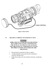
Page 31: ...OR SAND CAN PIT AND SCRATCH THE OPTICAL ELEMENTS AND DAMAGE THE MECHANICAL COMPONENTS UNLESS THE PRECAUTIONS GIVEN BELOW ARE OBSERVED 1 Ensure that the sacrificial window is inplace 2 Avoid pointing...

Page 32: ...and accessories after exposure to rain or high humidity and beforestorage 4 Do not store monocular in a wet carrying case 3 8 Operation in Salt Water Areas After exposure to salt water clean the unit...

Page 33: ...E PRIOR TO PLACING THE 14 INTO CARRYING CASE ENSURE THE 14 AND CASE ARE FREE OF DIRT DUST AND MOISTURE 5 Place the monocular accessories and cleaning supplies back into their storage carrying case It...

Page 34: ...35 This page intentionally left blank...

Page 35: ...CAREFULLY DO NOT SCRATCH THE EXTERNAL LENS SURFACES OR TOUCH THEM WITH YOUR FINGERS WIPING DEMIST SHIELD WITH LENS TISSUE WHILEWETORWITHWETLENSTISSUE CAN DAMAGE THE COATING 4 2 Deactivation Power dow...

Page 36: ...he optical surfaces using a circular motion Discard each lens tissue after one use to avoid transferring grit or foreign matter onto the lens surfaces If the lens remains dirty use a cotton swab light...

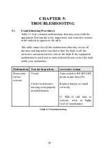
Page 37: ...ed to find the fault or all the corrective actions needed to correct the fault If the equipment malfunction is not listed or actions listed do not correct the fault notify your maintainer Malfunction...

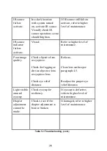
Page 38: ...r image quality Check objective lens or eyepiece Refocus Check for fogging or dirt on objective lens or eyepiece lens Clean lens surface per paragraph 4 5 Check eye relief distance Readjust for proper...

Page 39: ...bright room light not fluorescent light If damaged return to higher level of maintenance Place the objective lens cap on the objective lens Turn monocular ON and observe that it cuts off within 70 30...

Page 40: ...41 This page intentionally left blank...

Page 41: ...identify contact and order spare and or repair parts for the THE 14 A 2 Contact Information To order spare or repair parts for the THE 14 or any of your night vision products contact ACTinBlack Europ...

Page 42: ...43 This page intentionally left blank...

Page 43: ...ritten agreement The Purchaser shall grant ACTinBlack Europe S r l such adequate time and opportunity as deemed reasonable to remedy failures to meet the foregoing warranties To remedy such failures A...

Page 44: ...Material Authorization Number RMA Warranty and non warranty items returned to ACTinBlack Europe S r l for repair or replacement require a RMA Email info actinblack com with a serial number and detaile...

Page 45: ...Product name THE14 Trade name ACTinBlack Type of model to which this declaration relates is in conformity with the appropriate standards following the provisions of EMC Directive 2014 30 EU RoHS 2 Dir...

Page 46: ...ck Fulfils the essential requirements of MIL STD 810G The following standards were applied MIL STD_810G 501 5 High Temperature MIL STD_810G 502 5 Low Temperature MIL STD_810G 507 5 Humidity MIL STD_81...

Page 47: ...ACTinBlack Europe S r l 12 Rue de l Industrie L 3895 Foetz Grand Duchy of Luxembourg www actinblack com Part No MAN THE 14 001 June 2020...

Reviews: