background image

Marvair MAA/MGA Wall Mount AC Installation & Operation Manual

05/2023 Rev.21

21

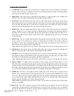
for W2 (auxiliary / emergency heat). When the SCKT Set is set to Y (yes) the electric heat will 

not be allowed to operate with the compressor in the heat-pump mode. When set to Y (yes) and 

upon a request for W2 (auxiliary / emergency heat) the compressor will shut off and the electric 

heat will operate.

Note: 

SCKT and EHDD cannot both be set to the Y (yes) selection at the same time. SCKT takes 

priority over EHDD. 

11. ODS Set:

 The ODS Set is used to set the Outdoor Sensor temperature for Heat-pump systems. 

When the system type is configured for Heat-pump (when setting 1 is set to HP), the ODS Set 

allows the outdoor sensor to be used to govern when electric heat is allowed to operate. When 

the outdoor temperature is below the ODS setpoint, the electric heat will be allowed to operate. 

The adjustable range is 0F-70F in 1F increments with a default setpoint of 50F.

12. ECONO Select:

 The ECONO Select is used to select whether the system has an economizer 

system installed or not. When set to the Y (yes) selection the system will include the economizer 

cooling algorithm within its sequence of operation and utilize the economizer package when 

conditions are favorable for economizer cooling. When set to the N (no) selection the system will 

only utilize the compressor for cooling operation. This setting is configured at the factory during 

production testing for the appropriate system type.

Note:

 When ECONO Set is set to Y (yes) the system must have an Enthalpy or Dry Bulb and 

Supply Air sensor connected and properly selected in setting 13 in order to operate in economizer 

cooling. The system will default to compressor cooling if any sensor becomes disconnected or 

faulty. Changing the ECONO Select to N (no) will disable economizer operation and the economizer 

function will be ignored.

13. Sensor Type:

 This setting is used for selecting the type of economizer sensor used EN (Enthalpy) or 

DB (Dry Bulb). The appropriate sensor must be connected and selected for economizer operation. 

This setting is configured at the factory during production testing for the appropriate sensor type.  

14. ECONO Set:

 This setting is used to set the economizer setpoint at which the economizer is 

allowed to operate for cooling.  When setting 13 is set for EN (Enthalpy), the selections are A= 

73F, B=70F, C=67F, D=63F and E=55F all at 50% relative humidity. The A – E selections will only 

be available when setting 13 is set to EN (Enthalpy). When setting 13 is set for DB (Dry Bulb), 

the selection is from 20F to 105F in 1F increments. The 20F-105F range will only be available 

when setting 13 is set to DB (Dry Bulb). 

15. MIN POS:

 The MIN POS setting is for setting the minimum position of the economizer or 

motorized damper. When set above 20 (2vdc) the damper will remain open to the selected position 

at all times, hence minimum position. The adjustable range is from 20 (2vdc) to 100 (10vdc) in 

1vdc increments.

16. W2 Speed:

 This is an independent setting for the speed at which the Indoor blower will operate 

upon a request for W2 (Electric heat) via Digital Input or Modbus. The default setting for the W2 

speed is 100% of maximum speed. The speed may be adjusted from 70-100% in 1% increments 

to meet desired airflow requirements.

Note:

 Adjusting the speed too low will result in increased supply air temperatures in electric heat 

mode. 

17. Dehum Speed:

 This is an independent setting for the speed at which the Indoor blower will operate 

upon a request for HUM (Dehumidification) via Digital Input or Modbus. The default setting for 

Summary of Contents for Marvair MAA1018A

Page 1: ...f this manual can be found at www Marvair com IMPORTANT This manual may include information for options and features which may not be included on the unit being installed Refer to the unit data label...

Page 2: ...T Laying it down on its side may cause oil to leave the compressor and breakage or damage to other components 3 TURN ELECTRICAL POWER OFF AT THE breaker or fuse box BEFORE installing or working on the...

Page 3: ...on the inside of the building adjacent to the thermostat END USER Retain these instructions for future reference Table of Contents Chapter 1 Marvair Wall Mount Air Conditioner Description Specificatio...

Page 4: ...omizer 14 Figure 1d Typical Electrical Schematic Model MAA Alternate Construction with Economizer 15 Figure 1e Typical Electrical Schematic Model MAA Alternate Construction with Economizer 16 Figure 2...

Page 5: ...x A for instructions on field installation of electric heat Marvair air conditioners feature an exclusive electronic control board The control board consolidates several of the electrical components a...

Page 6: ...R Crank Case Heater CCH T Hard Start w EFS U Hard Start w Hot Gas Bypass V Hard Start w Low Ambient CCH EFS W Low Ambient w CCH Y Low Ambient w CCH FCC Z Low Ambient w CCH EFS 1 Low Ambient w FCC 2 Lo...

Page 7: ...del INCHES MILLIMETERS PART NUMBER FILTERS PER UNIT MERV RATING MAA1018A 14 x 12 1 356 x 305 x 25 P 80122 1 N A MAA1020A 1024A 16 x 25 x 2 406 x 635 x 51 80137 1 8 MAA1024A 1030A 1036A B2 INTERNAL 16...

Page 8: ...of outside air into the enclosure when the outdoor air conditions are suitable to reduce the need for mechanical cooling save energy and extend compressor life Depending upon the options selected the...

Page 9: ...nly Used in specialty applications i e Magnetic Resonance Imaging MRI buildings to prevent magnetic voltage disturbance caused by compressor cycling Two hot gas bypass option packages are available to...

Page 10: ...s performance in hot ambient temperatures High Filtration Selected units are built with larger blowers motors for use with higher efficiency filters with MERV ratings of 11 13 and 14 when tested to AS...

Page 11: ...el Two stainless steel cabinet constructions are available the complete cabinet including most internal sheet metal or only the exterior sheet metal 1 7 Electrical Operation The compressor and condens...

Page 12: ...O C L L A N O D E R I U Q E R E B T O N Y A M R E T A E H E S A C K N A R C 3 T U O K C O L L L I W T I N U E H T D N A E C I W T D E N E P O S A H S P H E H T N E H W T L U A F E R U S S E R P H G I...

Page 13: ...E R I W P A T R E M R O S N A R T E G N A R O D N A D E R S R O S S E R P M O C L L A N O D E R I U Q E R E B T O N Y A M R E T A E H E S A C K N A R C 3 T U O K C O L L L I W T I N U E H T D N A E C...

Page 14: ...14 Marvair MAA MGA Wall Mount AC Installation Operation Manual 05 2023 Rev 21 Figure 1c Typical Electrical Schematic Economizer Model MAA Alternate Construction...

Page 15: ...Marvair MAA MGA Wall Mount AC Installation Operation Manual 05 2023 Rev 21 15 Figure 1d Typical Electrical Schematic Economizer Model MAA Alternate Construction...

Page 16: ...16 Marvair MAA MGA Wall Mount AC Installation Operation Manual 05 2023 Rev 21 Figure 1e Typical Electrical Schematic Economizer Model MAA Alternate Construction...

Page 17: ...le information to the end user Special features include 2 Stage operation with varying speed control to optimize latent and sensible capacity built in remote communication Modbus for monitoring and or...

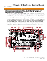
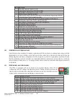
Page 18: ...d Stage 23 Control Board Power Indicator LED 2 2 Installation and Replacement The PCB is factory installed To install a replacement PCB use the six mounting holes along with the appropriate screw size...

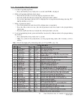
Page 19: ...Blower off delay in seconds 4 IBM Y1 Set 80 40 100 G Fan only and Y1 1st Stage Cooling Indoor Blower Speed Setting 5 IBM Y2 Set 100 40 100 Y2 2nd Stage Cooling Indoor Blower Speed Setting 6 OFM Select...

Page 20: ...ow pressureorhigh pressurelockout 6 OFM Select This setting allows the IBM Indoor Blower control signal to be configured for PWM or 0 10vdc control The default control output signal is PWM 7 OFM Set T...

Page 21: ...ystem will default to compressor cooling if any sensor becomes disconnected or faulty ChangingtheECONOSelecttoN no willdisableeconomizeroperationandtheeconomizer function will be ignored 13 SensorType...

Page 22: ...n 25 Software Version Number The software version of the 92589 control board will be displayed on the seven segment display This is for informational purposes only 2 4 Operation Power The Marvair PCB...

Page 23: ...DD Heat Pumps 5 0 Dehumidification Operation AC HP 5 1 Hot Gas Reheat 5 2 Electric Reheat 6 0 Refrigeration Protection 6 1 High Pressure lockout 6 2 Low Pressure Lockout Freeze Protection 6 3 Anti Sho...

Page 24: ...t priority This means that in any combination involving the G input the speed associated to Fan Only will never take precedence The priority list from Highest to Lowest goes as follows 1 Y2 Request 2...

Page 25: ...ns until the switch reopens at 290 PSIG These outputs function as described until the Cooling setpoint is satisfied This is considered as ON OFF fan cycle control and the PSC motor will not modulate N...

Page 26: ...Y1 speed since Y2 has higher priority These outputs remain energized until the cooling setpoint is satisfied Once the setpoint is satisfied the Compressor and the Outdoor fan outputs are de energized...

Page 27: ...e During the testing of the air conditioner at the factory the control board has been configured for the sensor type used in the system There should be no need to change the sensor configuration If an...

Page 28: ...cture and provides a signal to the economizer controller for modulating the position of the damper The default supply air temperature is 55F in economizer cooling and is not adjustable A disconnected...

Page 29: ...ill initiate a defrost cycle based on the time selected in the control board configuration menu setting 8 The defrost time intervals selections are 30 60 and 90 minutes and the factory default setting...

Page 30: ...r will remain off as long as the request for W2 is active Once the request for W2 satisfies the compressor will be allowed to operate The default setting for SCKT is N No the electric heat and compres...

Page 31: ...ne temperature of 80F and 115F Systems with PSC Outdoor Motors utilizes a Fan Cycle Switch which closes at 400 PSIG to energize the OFR outdoor fan relay to start the outdoor fan which runs until the...

Page 32: ...by protecting it from excessive short cycling When the compressor goes off due to any fault emergency or if the cooling heat pump heating setpoint is satisfied a built in 3 minute timer locks the comp...

Page 33: ...Modbus and the system will operate in normal cooling mode until the request for FC is satisfied Once satisfied the system will be allowed to return to economizer operation if conditions are favorable...

Page 34: ...pressor will not start makes excessive noise or will not pump return the unit to the freight carrier 3 2 Installation Requirements General 1 Inspect unit for completeness Check for missing parts e g h...

Page 35: ...m 24 inches 61 cm 6 inches 15 cm 1030A 1036A 30 inches 76 cm 18 inches 46 cm 24 inches 61 cm 6 inches 15 cm 1042A 1048A 1060A 2060A 30 inches 76 cm 30 inches 76 cm 24 inches 61 cm 6 inches 15 cm 1072A...

Page 36: ...an Non volatile program memory P N 50107 Grilles Wall Sleeves Supply Grilles For MAA1018A 17 x 5 432 mm x 127 mm P N 80682 For MAA1020A MAA1024A MAA1024A B2 20 x 8 508 mm x 203 mm P N 80674 For MAA103...

Page 37: ...his manual is intended for use by a qualified service agency that is experienced in such work is familiar with all precautions and safety procedures required in such work and is equipped with the prop...

Page 38: ...m of the unit Galvanized metal duct extensions should be used to simplify connections to duct work and grilles Use fabric boots to prevent the transmission of vibration through the duct system The fab...

Page 39: ...d on the wall You must stabilize the unit on the bracket with the lifting device or by some other means the bracket alone is not sufficient 3 Make sure that the duct flanges are properly aligned with...

Page 40: ...ressure drops and the discharge pressure rises when the compressor is energized An alternate method of verification for self contained system with small critical refrigerant charges where the installa...

Page 41: ...t meter set to the 300 volt scale measure voltage between terminal L1 on the compressor contactor of unit 1 and terminal L1 on the compressor contactor of unit 2 If voltage is present units are wired...

Page 42: ...industry set points to facilitate installation If desired each of the set points can be quickly and easily changed in the field by the installer It can be used with Marvair s unique vertical packaged...

Page 43: ...4 t l u a f n e g o r d y h a n o p u e d o m n o i t a l i t n e v k c a b d e e f s i h T C A V H d e t c e n n o c e h t m o r f g n i r o t i n o m s u t a t s r e z i m o n o c e r o f d e s u e...

Page 44: ...omizer Equipped models only To check the system operation under different ambient conditions the air temperature and enthalpy sensors must be tricked When outdoor ambient condi tions are higher than t...

Page 45: ...ays please exercise caution and good judgement when servicing the unit Use only safe and proven service techniques Use refrigeration goggles when servicing the refrigeration circuit WARNING The refrig...

Page 46: ...iction 2 Obstruction or leak in condensate pan 2 Check pan for leak or blockage 3 Unit is not level 3 Level unit F No space heating or reduced heating units equipped with resistance ele ments 1 Defect...

Page 47: ...rcuit 1 LP 2 Low Pressure Lockout Compressor Circuit 2 HP 1 High Pressure Lockout Compressor Circuit 1 HP 2 High Pressure Lockout Compressor Circuit 2 03 Low Voltage Brownout 16VAC or Less for 10 Minu...

Page 48: ...before restarting Condenser Periodicallyinspecttheoutdoorcondensercoilandthecabinetairreliefsfordirtorobstructions Remove foreign objects such as leaves paper etc If the condenser coil is dirty it ma...

Page 49: ...or any other material charges 2 Damages caused by shipping accident abuse negligence misuse fire flood or Acts of God 3 Damages caused by operating or staging the unit in a corrosive environment 4 Da...

Page 50: ...__________________________ Compressor Model No ______________________________________________ Serial No ______________________________________________ B Pre Start Up Is there any shipping damage Yes N...

Page 51: ...Deviation from avg voltage ______________volts Voltage imbalance 100 x Max Deviation avg Voltage ___________ A voltage deviation greater than 2 with the unit running should be addressed and corrected...

Page 52: ...ir DB Temp ________ ________ Evap Leaving Air WB Temp ________ ________ Heater Contactor Amps L1 ________ ________ Heater Contactor Amps L2 ________ ________ Heater Contactor Amps L3 ________ ________...

Page 53: ...__ Compressor Amps L3 ________ ________ Notes _________________________________________________________________________ _________________________________________________________________________ ______...

Page 54: ...the supply outlet duct flange on the unit The 1 25 4 mm clearance must extend on all sides of the supply duct for the first 3 feet 1 meter from the unit IMPORTANT Marvair requires a minimum of 1 25 4...

Page 55: ...ters 6 Install the two No 10 screws in the heater assembly plate 7 Install wire harness in hole provided in drain pan and then through filter bracket and then into control box 8 Wire the heater as sho...

Page 56: ...56 Marvair MAA MGA Wall Mount AC Installation Operation Manual 05 2023 Rev 21...

Reviews: