background image

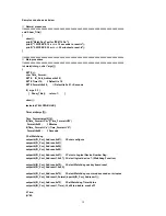
Sample code shows as below 
 
//  Normal procedure 
//=========================================================================== 
void Show_Title() 

   clrscr(); 
   printf("WatchDog Test for ITE8712F\n"); 
      printf("1. WDT.EXE 10 s ==--> 10 seconds to reset.\n"); 
      printf("2. WDT.EXE 20 m ==--> 20 minutes to reset.\n"); 

 
//=========================================================================== 
//  Main procedure 
//=========================================================================== 
int main(int argc, char *argv[]) 

   BYTE i,j; 
   char Time_Format; 
   BYTE  IO_Port_Address=0x2E; 
      BYTE Time=10; 

// Default is 10 

      BYTE Format=0x80; 

// Default is 0x01 = Seconds 

 
      if ( argc != 3 ) 
     {  Show_Title();   return 1;     } 
 
   clrscr(); 
 
   textcolor(BLINK); 
 
   Time=atoi(argv[1]); 
 
   Time_Format=argv[2][0]; 
   if(Time_Format=='m' || Time_Format=='M') 
 Format=0x00;  // 

Minutes 

   if(Time_Format=='s' || Time_Format=='S') 
 Format=0x80;  // 

Seconds 

 
   // Set Watchdog 
   outportb(IO_Port_Address,0x87);  // Enter configure 
   outportb(IO_Port_Address,0x01); 
   outportb(IO_Port_Address,0x55); 
   outportb(IO_Port_Address,0x55); 
 
      outportb(IO_Port_Address,0x07); 

// Point to Logical Device Number Reg. 

      outportb(IO_Port_1,0x07); // Select logical device 7, (Watchdog Function) 
 
      outportb(IO_Port_Address,0x72); 

// Select Watchdog use keyboard reset 

   outportb(IO_Port_1,0x40);   
 
      outportb(IO_Port_Address,0x72); 

// Select Watchdog count mode seconds or minutes 

   outportb(IO_Port_1,Format|inportb(IO_Port_1)); 
 
      outportb(IO_Port_Address,0x73); 

// Set Watchdog Timer Value 

      outportb(IO_Port_1,Time); // 0x00 to disable, max 0xFF 
 
      i=Time; 
   j=i*60; 


19

Summary of Contents for AR-B1572

Page 1: ...AR B1572 Fanless ISA Bus SBC with GX466 333MHz CPU User Guide Edition 1 0 Book Number AR B1572 06 10 25...

Page 2: ...D1 13 3 13 PARALLEL PORT CONNECTOR LPT1 14 3 14 KEYBOARD MOUSE CONNECTOR PS1 14 3 15 KEYBOARD MOUSE CONNECTOR KB MS1 14 3 16 KEYBOARD AND MOUSE LOCK UNLOCK HEADER KBJP1 MSJP1 14 3 17 RJ45 CONNECTOR LA...

Page 3: ...if you have not already installed this AR B1572 Check the packing list before you install and make sure the accessories are completely included AR B1572 CD provides the newest information regarding t...

Page 4: ...mponents Although areas with humid climates are much less prone to static build up it is always best to safeguard against accidents that may result in expensive repairs The following measures should b...

Page 5: ...and TFT interface with 24 bit panel specifications Ethernet connectivity comes from the RTL8100C 10 100 Ethernet controller The AR B1572 integrates ITE8888 PCI to ISA bridge in order to support ISA i...

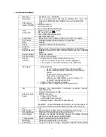
Page 6: ...O Chipset Winbond 8712F o Serial 1 high speed RS 232C serial port COM1 o Serial RS 232C 422 485 serial port COM2 with pin header o Parallel SPP EPP and ECP mode o Floppy Floppy disk drives 3 5 o K B M...

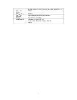
Page 7: ...0 degree white for PCB Operating Temp 0 60 Storage Temp 20 80 Operating Humidity 0 90 relative humidity none condensing Safety CE FCC class A Certified Supporting OS Windows NT4 0 2000 98 XP Linux Ver...

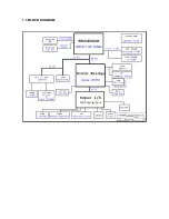
Page 8: ...1 3 BLOCK DIAGRAM...

Page 9: ...install the AR B1572 At first the layout of AR B1572 is shown and the unpacking information that you should be careful is described The jumpers and switches setting for the AR B1572 s configuration a...

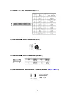
Page 10: ...SOUCE FOR LCD INVERTER INV1 PIN SIGNAL PIN SIGNAL 1 12V 2 12V 3 GND 4 5V 5 GND 6 NC 3 3 LCD CONNECTOR LCD Pin Signal Pin Signal 1 GND 2 CLK 3 GND 4 HSYNC 5 VSYNC 6 GND 7 B0 NC 8 B1 NC 9 B2 B0 10 B3 B...

Page 11: ...4 10 DATA 11 11 DATA 3 12 DATA 12 13 DATA 2 14 DATA 13 15 DATA 1 16 DATA 14 17 DATA 0 18 DATA 15 19 GROUND 20 N C 21 PDDREQ 22 GROUND 23 PDIOW 24 GROUND 25 PDIOR 26 GROUND 27 PIORDY 28 GROUND 29 PDDAC...

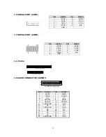
Page 12: ...6 CTSB 7 DTRB 8 RIB 9 GND 3 8 PC104 1 2 64 Pin PC 104 Connector 63 64 1 2 39 40 40 Pin PC 104 Connector 3 9 AUDIO CONNECTOR AUDIO1 1 2 Audio Connector 25 26 PIN SIGNAL PIN SIGNAL 1 CDINL 2 LININL 3 CD...

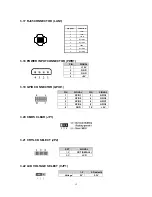
Page 13: ...2 5V 3 USB0 4 USB1 5 USB0 6 USB1 7 GND 8 GND 9 GND 10 GND 3 12 FLOPPY DISK DRIVE CONNECTOR FDD1 PIN SIGNAL PIN SIGNAL 1 GND 2 DRVDEN0 3 GND 4 NC 5 GND 6 NC 7 GND 8 INDEX 9 GND 10 MOA 11 GND 12 DSB 13...

Page 14: ...4 Ground 15 Data 6 16 Ground 17 Data 7 18 Ground 19 Acknowledge 20 Ground 21 Busy 22 Ground 23 Paper 24 Ground 25 Printer Select 26 No Used 3 14 KEYBOARD MOUSE CONNECTOR PS1 1 KDT 3 GND 2 MDT 6 MCLK 4...

Page 15: ...OWER INPUT CONNECTOR PWR1 PIN SIGNAL 1 12V 2 GND 3 GND 4 5V 3 19 GPIO CONNECTOR GPIO1 PIN SIGNAL PIN SIGNAL 1 GPIO1 2 GPIO5 3 GPIO2 4 GPIO6 5 GPIO3 6 GPIO7 7 GPIO4 8 GPIO8 9 GND 10 5V 3 20 CMOS CLEAR...

Page 16: ...N 3 25 POWER BUTTEN JP6 3 26 CF MASTER SELECT JP7 SET SIGNAL SHORT SLAVE OPEN MASTER 3 27 IT8888G STRAPING JP8 SET SIGNAL 1 2 ON IT8888G normal function OFF enable chip test with PCIRST 0 3 4 ON NO F...

Page 17: ...3 29 RS232 RS422 RS485 SWITCHING JP10 JP11 JP11 open JP11 short JP10 open RS232 RS422 JP10 short RS485 2W RS485 4W 17...

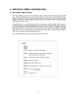
Page 18: ...he watchdog timer your program should trigger the watchdog timer every time before it times out After you trigger the watchdog timer the timer will be set to zero and start to count again If your prog...

Page 19: ...if Time_Format s Time_Format S Format 0x80 Seconds Set Watchdog outportb IO_Port_Address 0x87 Enter configure outportb IO_Port_Address 0x01 outportb IO_Port_Address 0x55 outportb IO_Port_Address 0x55...

Page 20: ...hile 1 gotoxy 20 10 if Time_Format m Time_Format M cprintf After d Second will reset the system j j if Time_Format s Time_Format S cprintf After d Second will reset the system i i delay 900 return 0 2...

Page 21: ...in your computer system and set the system clock and error handling If the motherboard is already installed in a working system you will not need to select this option You will need to run this Setup...

Page 22: ...he device information manually You will be asked to enter the following items CYLS Number of cylinders HEAD Number of read write heads PRECOMP Write precompensation LANDING SONE Landing zone SECTOR Nu...

Page 23: ...tions for this field are Enabled and disabled By default the field is set to Disabled Swap Floppy Drive The options for this field are Enabled and disabled By default the field is set to Disabled PS 2...

Page 24: ...in to specify your setting for power management Power Setup Power Management Enable this field to support Power Management function ACPI Function Enable this function to support ACPI Advance Configura...

Page 25: ...t and their addresses The default values for this port is Parallel Port 378 IRQ7 Parallel Port Mode This field allow you determine parallel port mode function SSP Standard Parallel Port EPP Enhanced P...

Page 26: ...t to this value PnP PCI Setup Reset Configuration Data Thus field allows you to determine whether to reset the configuration data or not The default value is Disabled Resources Controlled By This PnP...

Page 27: ...parameters of the hardware monitoring function feature of the motherboard The values are read only values as monitored by the system and show the PC health status Shutdown Temperature This field allow...

Page 28: ...s PCI Plug And Play First Second Third Boot Device These fields determine the device that the system searches first for an operating system The option available include Hard Disk CDROM USB FDD USB CDR...

Page 29: ...you type N you will return to setup utility Load Optimized Defaults This option allow you to load the default values to your system configuration These default settings are optimal and enable all high...

Page 30: ...type the AWDFLASH and press ENTER A AWDFLASH Step 4 A window will appear and ask you to type the complete BIOS file xxxxxx BIN and Note press ENTER Step 5 Then it will ask whether you save the old BI...

Page 31: ...es 0080 0090 Direct Memory Access controller 0091 0093 Motherboard resources 0094 009F Direct Memory Access controller 00A0 00A1 Programmable interrupt controller 00A2 00BF Motherboard resources 00C0...

Page 32: ...01 Standard 101 102 Key or Microsoft Natural Keyboard 02 Programmable interrupt controller 03 Communication Port COM2 04 Communication Port COM1 05 Standard Enhanced PCI to USB Host Controller 05 Sta...

Reviews: