4. WATCHDOG TIMER CONFIGURATION
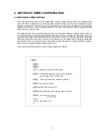
4.1 WATCHDOG TIMER SETTING
The WDT (Watch Dog Timer) is used to generate a variety of output signals after a user programmable
count. The WDT is suitable for use in the prevention of system lock-up, such as when software becomes
trapped in a deadlock. Under these sorts of circumstances, the timer will count to zero and the selected
outputs will be driven. Under normal circumstance, the user will restart the WDT at regular intervals
before the timer counts to zero.
The watchdog timer is a circuit that maybe used from your program software to detect crash or hang up.
The Watchdog timer is automatically disabled after reset. Once you enabled the watchdog timer, your
program should trigger the watchdog timer every time before it times out. After you trigger the watchdog
timer, the timer will be set to zero and start to count again. If your program fails to trigger the watchdog
timer before times out, it will generate a reset pulse to reset the system or trigger the IRQ 9 signal in
order to tell your system that the watchdog time is out.
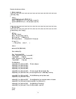
User could test watchdog function under ‘Debug’ program as follows:
C:>debug
o 2E 87
o 2E 87
o 2E 55
o 2E 55 Extended Functions Enable Register
o 2E 07 ;EFIR=EFER (Extended Functions Index Register)
point to Logical Device Number Reg.
o 2F 07 ; Select logical device 8, (Watchdog Function)
o 2E 23 ; Device Active register
o 2F10 ;update CR30 with value 01H
o 2E 72 ; Select Watchdog count mode seconds or minutes
o 2F C0 unit select C0
Æ
second
40
Æ
minute
o 2E 73
o 2F 00 timer set 00
Æ
FF
q
18
Summary of Contents for AR-B1572
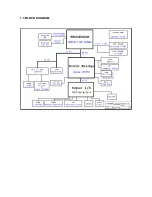
Page 8: ...1 3 BLOCK DIAGRAM...


