background image

ANR-C62xN1 Series

51

www.acrosser.com

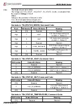
Note: 

The Mode bits are set to 000b. 
The Voltage (ex.+12V_VOUT , 3V3_VOUT , 5V_VOUT), in volts, is calculated from 
the equation: Voltage = V x 2

n


Where: 
Voltage is the parameter of interest in volts;  
V is a 16 bit unsigned binary integer; and 
N is a 5 bit two’s complement binary integer.

Contents in 79h (STATUS_WORD) Command Code:

Byte

Bit Number

Status Bit Name

Meaning

Low

[7:0]

Reserved

Return=0

High

7

VOUT

+12V Output voltage warning has 

occurred = 1 ; Normal = 0

High

6

IOUT

+12V Output current warning has 

occurred = 1 ; Normal = 0

High

5

Reserved

Return=0

High

4

3V3/5V_VOUT&IOUT

3V3/5V Output voltage warning has 

occurred =1 ; Normal = 0

High

3

POWER_ GOOD#

The POWER_GOOD signal is OK = 1 ; 

FAIL = 0

High

[2:0]

Reserved

Return=0

Contents in 7Ah (STATUS_VOUT) Command Code:

Bit Number

Status Bit Name

Meaning

7

Reserved

Return=0

6

+12V_OV_WARNING

VOUT > 13.0V = 1 ; Normal = 0

5

+12V_UV_WARNING

VOUT < 11.0V = 1 ; Normal = 0

[4:0]

Reserved

Return=0

Contents in 7Bh (STATUS_IOUT) Command Code:

Bit Number

Status Bit Name

Meaning

[7:6]

Reserved

Return=0

5

+12V_OC_WARNING

+12V_IOUT > Max Current of 

110%@1Sec = 1 ; Normal = 0

[4:0]

Reserved

Return=0

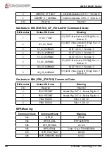
Contents in 7Dh (STATUS_TEMPERATURE) Command Code:

Bit Number

Status Bit Name

Meaning

[7:3]

Reserved

Return=0

Summary of Contents for ANR-C62-N1 Series

Page 1: ...Acrosser Technology Co Ltd www acrosser com ANR C62xN1Series Networking 2U Rackmount Server Intel Xeon C627 C622 PCH 8x Acrosser Swappable Expansion NIM for 1G 10G 25G 40G Fiber Copper LAN Bypass 2x SFP 10G Fiber 1x Management Port ...

Page 2: ... Ltd Trademarks The product names appear in this manual are for identification purpose only The trademarks and product names or brand names appear in this manual are the property of their respective owners Purpose This document is intended to provide the information about the features and use of the product Audience The intended audiences are technical personnel not for general audiences WARNING D...

Page 3: ... 2 1 Package List 17 2 1 1 Screw List 18 2 2 Slide rail Assembly 21 2 3 PCIe Card Installation 25 3 BIOS Settings 30 3 1 Main Setup 30 3 2 Advanced Setup 31 3 2 1 Trusted Computing 32 3 2 2 OnBoard Bypass Controller 32 3 2 3 W83627DHG Super IO Configuration 33 3 2 4 W83627DHG HW Monitor 34 3 2 5 Serial Port Console Redirection 35 3 2 6 USB Configuration 36 3 2 7 Network Stack Configuration 37 3 2 ...

Page 4: ... 1 4 LCD Control Module 44 4 1 5 Power Supply Unit 45 4 1 6 Chassis Opened 45 4 2 File Descriptions 45 4 2 1 GPIO Watchdog LCD Control Module 45 4 3 API List and Descriptions 46 4 3 1 GPIO 46 4 3 2 Watchdog 46 4 3 3 LCD Control Module 47 4 3 4 Power Supply Unit PMBUS 48 4 3 5 Pmbus Command Code Summary 49 4 3 6 Chassis Opened 53 4 3 7 Notes 53 5 FAQ 55 Q 1 Where can I find the serial number of thi...

Page 5: ...rity Gateway Se GW Unified Threat Management UTM and Network Functions Virtualization NFV As excellence network appliances ANR C627 622N1 series support dual socket Intel Xeon Scalable processors 24 RDIMM LRDIMM DDR4 2666 dual on board SFP 10G fiber and 8 Expandable Network Interface Modules NIMs for 1G 10G 40G fiber Copper Bypass various options Strong networking ability can meet most of enterpri...

Page 6: ...ce Ethernet on board 2x 10G Fiber SFP 1 2 via Intel PCH C62x series 1x RJ 45 Copper LAN port Storage HDD Bay ANR C62xN1 4x 2 5 SATA3 Hot swappable RAID 0 1 5 10 ANR C62xN1U 2x U 2 NVMe Hot swappable RAID 1 mSATA 1x mSATA Socket Support full size module CFast 1x CFast Socket Others Watchdog Timer Software Programmable 0 255 Secs Battery Lithium Battery 3V 220mAH CR2032 Hardware Monitoring CPU Volta...

Page 7: ...undant ATX PSU 800W Power Requirements ATX Circuit as AT Mode with Power Switch EMC Safety Certification CE FCC Class A RoHS 2 cULus Vibration Test IEC 60068 2 64 5 500Hz 3GRMS Drop Test ISTA 2A 2006 1 3 Packing List Check if the following items are included in the package Item Q ty ANR C62xN1 Series System 1 CD Utility 1 RJ45 console cable RJ45 DB9 1 USB console cable Micro B Type A 1 Power Cord ...

Page 8: ...ANR C62xN1 Series 8 Acrosser Technology Co Ltd 1 4 Layout Dimension Illustration model ANR C62xN1 with 8x optional LAN modules 440 00 88 50 670 00 ...

Page 9: ...1 Module A Network expansion module connector Available LAN Modules Note The model name type number or layout design of these options might change due to product revision 1 ACC NM1Z1 01C8B 1G Copper x8 RJ 45 w 4 pair Bypass 2 ACC NM1Z1 01C8 1G Copper x8 RJ 45 ...

Page 10: ...62xN1 Series 10 Acrosser Technology Co Ltd 3 ACC NM1Z1 01F8 1G Fiber x8 SFP 4 ACC NM1Z1 01H8B 1G Hybrid x8 SFP RJ 45 w 2 pair Bypass 5 ACC NM1Z1 01H8 1G Hybrid x8 SFP RJ 45 6 ACC NM1Z1 10F2 10G Fiber x2 SFP ...

Page 11: ...ANR C62xN1 Series 11 www acrosser com 7 ACC NM1Z1 10F4 10G Fiber x4 SFP 8 ACC NM1Z1 40F1 40G Fiber x1 QSFP 9 ACC NM1Z1 40F2 40G Fiber x2 QSFP 10 ACC NM1Z1 01C4B 1G Copper x4 RJ 45 w 2 pair Bypass ...

Page 12: ...ANR C62xN1 Series 12 Acrosser Technology Co Ltd 11 ACC NM1Z1 01C4 1G Copper x4 RJ 45 12 ACC NM1Z1 01F4 1G Fiber x4 SFP ...

Page 13: ... 5 3 SFP 10GbE LAN Ports LED Light Status Blue Blue On 10Gbps Off 1Gbps or below If this LAN port funtion fail after connected a 1GbE module you may try the following steps Step 1 Remove the 1GbE module from the LAN port Step 2 Disable the LAN port function Step 3 Enable the LAN port function Or you may remove the 1GbE module from the LAN port and then restart the system ...

Page 14: ...e M USB Micro USB For Console Function Note Either M USB or RJ45 console can only be used only one at a time Reset System Reset Button Console RJ45 Pin Signal Pin Signal 1 RTS 5 GND 2 DTR 6 SIN 3 SOUT 7 DSR 4 GND 8 CTS LAN LED Light Status LED2 Off 10Mbps Orange 100Mbps Green 1000Mbps LED1 Yellow Link Active Off LAN Off ...

Page 15: ... 5 5 LCM Display Navigation Joystick Indicators IPMI HDD Navi Joystick PWR LCM LCM Display 128 32 Pixels Graphic mode only Navigation Joystick LCM menu control buttons Up Down Left Right Center IPMI IPMI indicator Green HDD HDD activity indicator Yellow PWR Power indicator Green ...

Page 16: ... Slot SYSFAN5 SYSFAN2 SYSFAN1 SYSFAN6 SYSFAN3 SYSFAN4 Expansion Card Slot 1x PCI express card insert slot AC Inlets 1 1 CRPS 2U Redundant ATX PSU System Fan 4x Hot swappable Smart Cooling Fans with 2 color LED Green Normal Orange Warning USB 2x USB 2 0 ports VGA VGA connector Power Switch Power on off switch ...

Page 17: ... Installation To mount this server into a rack you will need to do some preparation 2 1 Package List Check the following items Item Description Q ty RJ45 console cable RJ45 DB9 1 USB console cable Micro B Type A 1 Ear Bracket 2 Screw Pack 1 ...

Page 18: ...ew List This is a bag of screws and sponges Item Description Q ty 1 M4x6 black For ear bracket 8 2 M3 Screw For 2 5 HDD with sponge yellow 8 3 6 32 Screw For 3 5 HDD with sponge yellow 8 4 Sponge yellow For 2 5 3 5 HDD 8 5 M3x4 sliver For HDD bay 2 5 7mmx4 16 ...

Page 19: ...ANR C62xN1 Series 19 www acrosser com 1 Ear brackets 2 2 5 HDD with sponge ...

Page 20: ...ANR C62xN1 Series 20 Acrosser Technology Co Ltd 3 3 5 HDD with sponge 5 7mm HDD bay with screws ...

Page 21: ...ANR C62xN1 Series 21 www acrosser com 2 2 Slide rail Assembly 1 Slide rail Screw 2 Screw List ...

Page 22: ...n rack mounted Step 1 Insert M5 Nut to the front right left rear right left of the rack Step 2 Fasten both inner brackets by M4x4 screws to each of the server s left and right side Step 3 Fasten both ear brackets by M4x6 black screws to each of the server s left and right side ...

Page 23: ...ANR C62xN1 Series 23 www acrosser com Step 4 Install the slide rail with M5x15 screws on both sides of the rack The length can be adjusted with the 7mm nut ...

Page 24: ...ANR C62xN1 Series 24 Acrosser Technology Co Ltd Step 5 Slide the server in Note The slide rail will stop and lock in center position Poke to push it in or pull out ...

Page 25: ...p 1 Open the top cover The red line frame is marked as the position to insert the add on PCIe card Remove the 2 screws shown in the red circle to remove the bracket Step 2 Remove the 7 screws shown in the red circle of the next three figures and then remove the bracket ...

Page 26: ...ANR C62xN1 Series 26 Acrosser Technology Co Ltd ...

Page 27: ...ANR C62xN1 Series 27 www acrosser com Step 3 Remove the 2 screws shown in the figure below and remove the 2 bracket plates Step 4 Insert the add on PCIe card into position ...

Page 28: ...ANR C62xN1 Series 28 Acrosser Technology Co Ltd Step 5 Lock all the screws back ...

Page 29: ...ANR C62xN1 Series 29 www acrosser com Step 6 Adjust the bracket position according to the length of add on card to clamp the card firmly Lock the screws ...

Page 30: ...nd in each of the BIOS menus The following topics are covered Main Setup Advanced Setup IntelRC Setup Processor Setup Security Setup Boot Setup Save Exit Setup Once you enter the Award BIOS CMOS Setup Utility the Main Menu will appear on the screen Use the arrow keys to highlight the item and then use the Pg Up Pg Dn keys to select the value you want in each item 3 1 Main Setup This setup menu dis...

Page 31: ...uper IO setting W83627DHG HW Monitor This option configures checks the status of Harwdare Monitor Value Serual Port Console Redirection This option configures the console redirection settings USB Configuration This option configures the USB parameters Network Stack Configuration This option configures the IPV4 IPV6 parameters CSM Configuration This option configures Enable Disable the Option ROM a...

Page 32: ...on Security Device Support Enables or Disables BIOS support for security device O S will not show Security Device TCG EFI protocol and INT1A interface will not be available SHA 1 PCR Bank Enables or Disables SHA 1 PCR Bank SHA256 PCR Bank Enables or Disables SHA256 PCR Bank 3 2 2 OnBoard Bypass Controller ...

Page 33: ...econds the system will be shut down 3 2 3 W83627DHG Super IO Configuration Serial Port Select Enabled to enable the onboard serial port Change Settings This option specifies the base I O port address and the interrupt Request address of Serial Port Select Auto to let the BIOS automatically assign the base l O and IRQ address ...

Page 34: ...rget Temperatur and FAN Tolerance manually If CPU temp is lower than target temp tolerance the fan will run at low fan speed If CPU temp ishigherer than target temp tolerance the fan will run at full fan speed Manual Mode You can set fixed fan speed FAN Target Temperature Input a target temperature between 0 127 C FAN Tolerance Input a target temperature tolerance ...

Page 35: ... Enabled you can select a COM Port to be used for Console Redirection Console Redirection Settings Set the Baut rate and Console Type Terminal Type Use this item to select the preferred terminal emulation type for out of band management Bits per second Use this item to select the serial port transmission speed The speed used in the host computer and the client computer must be the same Long or noi...

Page 36: ...a loss from buffer overflow When sending data if the receiving bufers are full a stop signal can be sent to stop the datalow Once the bufers are empty a start signal can be sent to restart the flow Hardware flow uses two wires to send start stop signals The options include None and HardwareRTS CTS VT UTF8 Combo Key Support Use this item to enable or disable the VT UTF8 Combo Key Support for ANSI V...

Page 37: ... that do not support XHCI Extensible Host Controller Interface hand off The XHCI ownership change should be claimed by the XHCI driver USB Mass Storage Driver Support Select Enabled for USB Mass Storage Driver Support Port 60 64 Emulation Select Enabled for I O port 60h 64h emulation support which in turn will provide complete legacy USB keyboard support for the operating systems that do not suppo...

Page 38: ...ot option filter Use this item to control the Legacy UEFI memory sequence Options are UEFI and Legacy Legacy only UEFI only Network This item provides control of the operation UEFI and regular PXE Storage Video ramdomly read memory OpROM Options are UEFI Legacy Do not Launch Network Set The Network boot Mode UEFI Legacy Storage Set The Vbios Mode UEFI Legacy Video Set The Boot Mode Legacy Boot or ...

Page 39: ... Series 39 www acrosser com 3 3 IntelRCSetup 3 3 1 PCH SATA Configuration Port 1 4 Enable Disable Port 1 2 3 4 device Hot Plug Enable Disable HDD Hot Plug function SATA Device Type Select SATA Device Type HDD SSD ...

Page 40: ...rocessor Configuration Hyper Threading All The Hyper Threading Technology allows a single processor to execute two or more separate threads concurrently When hyper threading is enabled multi threaded software applications can execute their threads thereby improving performance VMX Enable Disable the Vanderpool Technology This will take effect after rebooting the system ...

Page 41: ...Enable Disable the Intel VT for Directed I O VT d support function by reporting the I O device assignment to VMM through DMAR ACPI Tables Interrupt Remapping Enable Disable the interrupt remapping support function PassThrough DMA Enable Disable the Non Isoch VT_D Engine PassThrough DMA support function ...

Page 42: ... User Password 3 6 Boot Setup Bootup NumLock State This feature selects the Power on state for the Numlock key Quiet Boot Use this feature to select the screen display between POST messages or the OEM logo at bootup Select Disabled to display the POST messages Select Enabled to display the OEM logo instead of the normal POST messages ...

Page 43: ...eset Select this option to quit the BIOS Setup without making any permanent changes to the system configuration and reboot the computer Select Discard Changes and Exit from the Exit menu and press Enter Restore Defaults To set this feature select Restore Optimized Defaults and press Enter These are factory settings designed for maximum system performance but not for maximum stability Boot Override...

Page 44: ...igure and to access the Watchdog timer The Watchdog timer can be set to 1 255 seconds Setting the timer to zero disables the timer The remaining seconds of the timer to reboot can be read from the timer 4 1 4 LCD Control Module The LCM short for LCD Control Module APIs provide interfaces to control the module By invoking these APIs programmers can implement the applications which have the function...

Page 45: ...ened status 2 Set chassis opened Enabled or Disabled 4 2 File Descriptions 4 2 1 GPIO Watchdog LCD Control Module 1 TestUtility exe The GPIO Watchdog Power Supplay Unit LCM Control Module and chassis open Graphic user interface bin binary 2 TestUtility The GPIO Watchdog Power Supplay Unit LCM Control Module and chassis open Console user interface bin binary 3 Libw83627 h This file includes the dec...

Page 46: ...n int value Description Set the status of GPIO Output value Parameters Set value 0 is Low 1 is High Return Value If the function sets the values successfully it returns 0 or 1 any other returned value stands for error 4 3 2 Watchdog Syntax Void wdt_start int _timevalue Description This function gets the watchdog timer register to the time value and starts to count down Parameters The parameter val...

Page 47: ... char pointer 512bytes pointe hex Return Value None Syntax Void get_lcm_mode_type unsigned char data Description This function can get lcm type mode Parameters unsigned char pointer 10bytes data the lcm type mode will save to pointer data Return Value None Syntax int get_lcm_key_code unsigned char data Description Scan the LCM and return the identification of the pressed direction key Parameters u...

Page 48: ... can get LCM PIC Version Parameters lcm pic version will save the unsigned char pointer parameters Return Value None Syntax Void set_lcm_default_graphic void Description This function can set LCM setting to default Parameters None Return Value None 4 3 4 Power Supply Unit PMBUS Syntax float pmbus_read_vout_12V void Description This function can get power supply unit Vout 12V Parameters None Return...

Page 49: ...Data Bytes 03h CLEAR_FAULTS 1 Send Byte 0 20h VOUT_MODE Read Byte 1 79h STATUS_WORD Read Word 2 7Ah STATUS_VOUT Read Byte 1 7Bh STATUS_IOUT Read Byte 1 7Dh STATUS_TEMPERATURE Read Byte 1 80h STATUS_OF_3V3 And 5V Read Byte 1 8Bh READ_ 12V_VOUT Read VOUT Mode 2 8Ch READ_ 12V_IOUT Read Linear 2 8Dh READ_TEMPERATURE_1 2 Read Linear 2 96h READ_ 12V_POUT Read Linear 2 99h MFR_ID Read ASCII 6 9Ah MFR_MOD...

Page 50: ...ion 79h STATUS_WORD Latch 7Ah STATUS_VOUT Latch 7Bh STATUS_IOUT Latch 7Dh STATUS_TEMPERATURE Latch 80h STATUS_OF_3V3 And 5V Latch B0h PSU_STATUS Automatic recovery Note 2 READ_TEMPERATURE_1 should provide the PDB Inlet Ambient temperature Note 3 Read Total Power command only at 12 V 3V3 5V total power Note 4 Buzzer will alert when any PSU fault occurs Write 0x20 command in PMBus will be able to mu...

Page 51: ...rrent warning has occurred 1 Normal 0 High 5 Reserved Return 0 High 4 3V3 5V_VOUT IOUT 3V3 5V Output voltage warning has occurred 1 Normal 0 High 3 POWER_ GOOD The POWER_GOOD signal is OK 1 FAIL 0 High 2 0 Reserved Return 0 Contents in 7Ah STATUS_VOUT Command Code Bit Number Status Bit Name Meaning 7 Reserved Return 0 6 12V_OV_WARNING VOUT 13 0V 1 Normal 0 5 12V_UV_WARNING VOUT 11 0V 1 Normal 0 4 ...

Page 52: ...ormal 0 3 5V_OV_WARNING VOUT 5 5V 1 Normal 0 2 5V_OC_WARNING 5V_IOUT Max Current of 110 1Sec 1 Normal 0 1 3V3_OV_WARNING VOUT 3 6V 1 Normal 0 0 3V3_OC_WARNING 3V3_IOUT Max Current of 110 1Sec 1 Normal 0 Contents in B0h PSU_STATUS Command Code Bit Number Status Bit Name Meaning 7 4 Reserved Return 0 3 PSU2 PRESENT Module Plug OUT 1 Module Plug IN 0 2 PSU1 PRESENT Module Plug OUT 1 Module Plug IN 0 ...

Page 53: ...ed Parameters 0 Disabled 1 Enabled Return Value None 4 3 7 Notes Syntax int libw83627_init void Description use the watchdog gpio function before must be call this function first Parameters None Return Value 0 Successful 1 Fail Syntax void lib_close void Description if watchdog gpio fuction not use on your program please call this function Parameters None Return Value None Syntax void i2c_init voi...

Page 54: ... if the psu i2c psu pmbus chassis lan bypass these function not use on your program please call this function Parameters None Return Value None Syntax void CloseSerialPort void Description if lcm function not use on your program please call this function Parameters None Return Value None ...

Page 55: ...w acrosser com 5 FAQ Q 1 Where can I find the serial number of this product The serial number S N is a label printed with alpha numeric character You can find the S N label on the bottom of this product or on its packing box ...

Page 56: ...ail Address Your Company Address Acrosser Model Name Acrosser Serial Number Describe System Configuration CPU Type Memory Size Storage Device e g HDD CF or SSD Additional Peripherals e g Graphic Card Operating System Version e g Windows 7 Embedded Special API or Driver If yes please provide it for debug Running Applications Others Describe Your Problems or Questions Send the above information to o...

Page 57: ...l Zone Tairan 8th Road Futian District Shenzhen China Postal 518040 TEL 86 755 83542210 FAX 86 755 83700087 Acrosser Nanjing Office 欣扬通电子有限公司 南京办事处 江苏省南京市江宁区天元东路228号504室 邮编 211100 Room 504 No 228 Tian Yuan East Rd Jiang Ning Dist Nanjing City Jiangsu Province China Postal 211100 Mobile 13611932003 TEL 86 025 86137002 FAX 86 025 86137003 Acrosser Beijing Office 欣扬通电子有限公司 北京办事处 北京市昌平区沙河镇沙阳路巩华新村8号楼2单...

Reviews: