Model TT339-0700
4-Wire Isolated Frequency Transmitter w/USB
Acromag, Inc. Tel: 248-295-0880
[
11
]
http://www.acromag.com
Optional Bus & Redundant Power Connections
Power is normally connected to the TB4 power terminals of the transmitter as
shown on the previous page. However, this transmitter is equipped to be optionally
powered via its DIN rail bus connector provided (Acromag 1005-063), when mated
to an optional plug-in terminal block (Acromag 1005-220 or 1005-221). Power input
via the bus connector terminal is diode-coupled to the same point as transmitter
power connected at TB4 power.
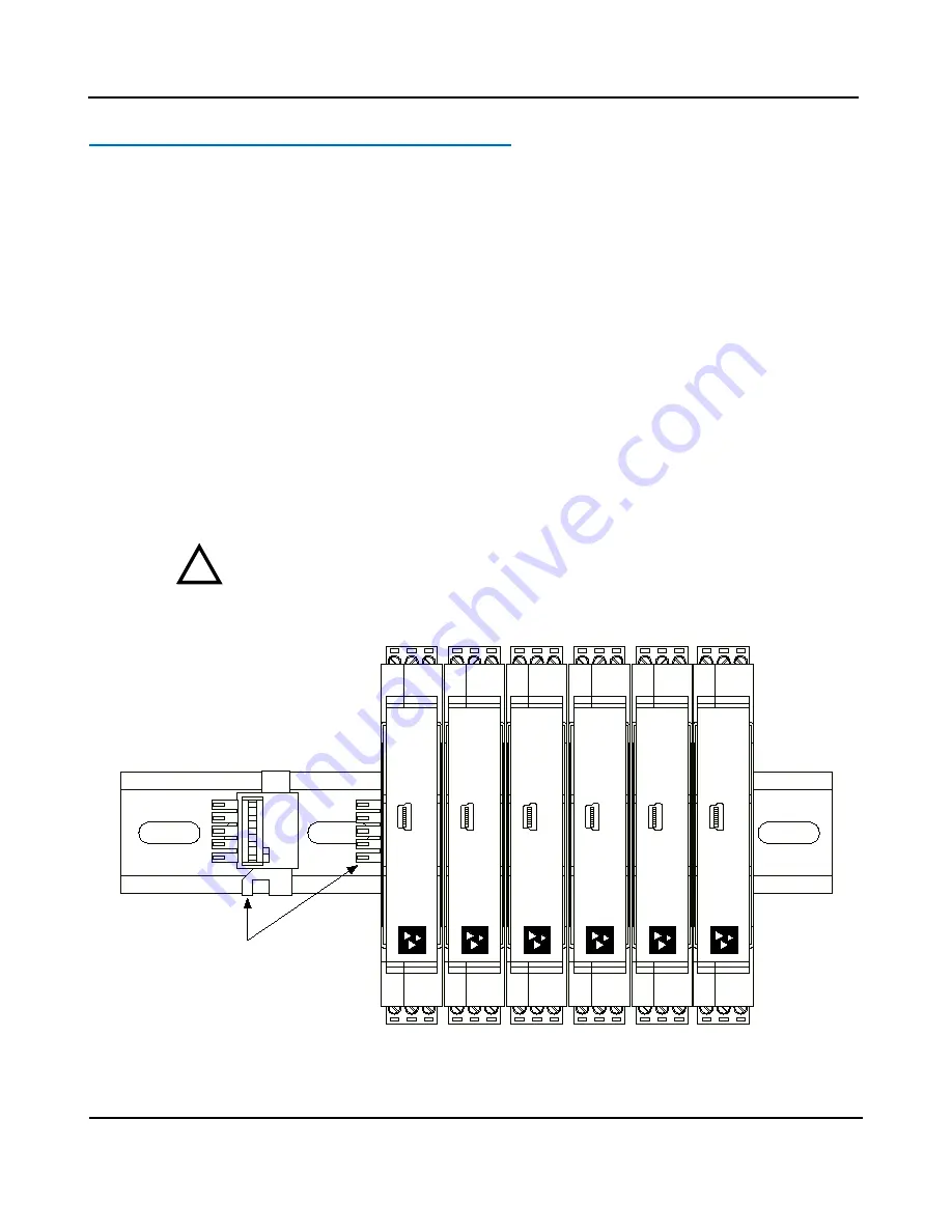
Multiple modules may be powered by snapping them together along the DIN rail
bus, then using the mating terminal block shown at left (select a Left or Right side
connector). While the intent of the bus power connector is to allow several modules
to conveniently share a single supply, the bus power connector may also be used to
redundantly power modules, allowing a backup supply to maintain power to the
module(s) should the main supply at TB4 fail.
This transmitter comes equipped with the bus connector 1005-063 shown below.
This connector allows modules to snap together, side-by-side, along the DIN rail and
share these connections. To complete connection to power, an optional bus
terminal block is needed (Acromag 1005-220 for left-side, or 1005-221 for right-side
connections). Refer to the figure on the following page which shows how to wire
power to the optional bus connector using these connectors.
Important – End Stops:
If this module uses the optionally powered (or redundantly
powered) via the DIN rail bus for hazardous location installations (Class I, Division 2
or ATEX Zone 2) it must use two end stops (Acromag 1027-222) to secure the
terminal block and module (not shown).
35mm DIN Rail
TT300
Series
USB
TT300
Series
USB
TT300
Series
USB
TT300
Series
USB
TT300
Series
USB
TT300
Series
USB
DIN Rail Bus Connector
Acromag 1005-063
(Included with Module)
!


