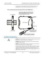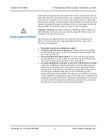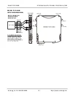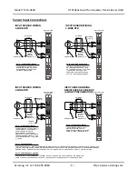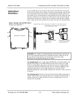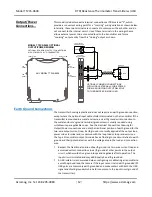
Model TT235-0600
RTD/Resistance Thermometer Transmitter w/USB
Acromag, Inc. Tel: 248-295-0880
- 15 -
http://www.acromag.com
[
15
]
https://www.acromag.com
Quick Overview
–
Windows
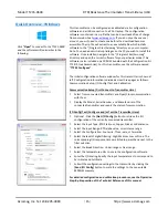
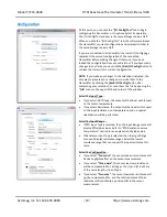
Click
“Open”
to connect to the TT235-0600
and the software will look similar to the
following:
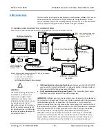
This transmitter can be configured and calibrated via its configuration
software and a USB connection to a PC or laptop. The configuration
software is contained in a zip file that can be downloaded free of charge
from our web site at
. If you do not yet have a user
account, you will need to create one before the download becomes
accessible. The zip file will extract to an executable file which installs
software to the “/Program Files/Acromag” directory on your computer.
Note: You need administrator privileges on the PC you wish to install this
software. Once installed, navigate to the “/Program Files/Acromag”
directory and open the correct software for your particular model. This
software is also included on a CDROM bundled with the Configuration Kit
TTC-SIP (see Accessories). For this transmitter, use the software named
“
TT235 Config.exe
”.
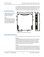
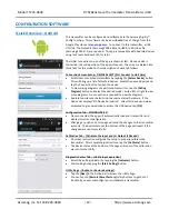
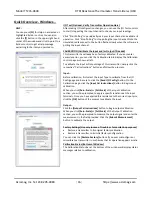
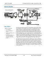
The initial configuration software window for this transmitter is shown at
left. Configuration information is divided across three pages as follows:
Communication Setup, I/O Config/Test, and Calibration.
Communication Setup (First Connect to Transmitter Here)
Select from connected transmitters and Open/Close communication
with them.
Display the Model, Serial Number, and Manufacturer of the
connected transmitter and report the status of communication.
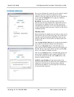
I/O Config/Test (Configure and/or Test the Transmitter Here)
Optional - Click the
[Get I/O Config]
button to retrieve the I/O
configuration of the currently connected transmitter.
Select the Input Type: RTD Platinum, Copper, Nickel, or Resistance.
Select the Input Range: RTD alpha value, or resistance range.
Select the Configuration: Four-wire, Three-wire, or Two-wire.
Select the level of digital filtering: High, Medium, Low or None. The
corresponding I/O response times are listed in parenthesis next to the
filter selection.
Select the Break Direction: Under-range or Over-range.
Select the temperature units to use in the configuration software.
•
Enter the I/O Scaling. Specify the input temperatures to correspond to
Zero-Scale and Full-Scale.
Submit the configuration settings to the transmitter by clicking the
[Send I/O Config]
button to write the settings to the non-volatile
EEPROM memory.
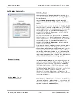
For detailed configuration and calibration procedures, see the Operation
Step-By-Step section of the Technical Reference of this manual.


